In a storage area network, a single mismatched fiber channel SFP can turn “green” ports into intermittent I/O stalls, CRC errors, or full link flaps. This article walks you through a real SAN deployment case and the engineering decisions that kept latency stable and uptime high. It helps storage, network, and field engineers selecting FC optics for production arrays, switches, and host HBAs.

Problem to solve: FC links that flap after optic swaps
In our case, a mid size enterprise refreshed aging FC transceivers across a production SAN fabric. Within 48 hours of swapping optics, two edge switches began showing intermittent loss of signal during peak backup windows, even though the inventory spreadsheet showed “compatible” part numbers. The storage team reported sporadic path failures on two critical database clusters, and the network team saw rising FEC/CRC style error counters typical of marginal optical budgets. The root cause was not just “bad optics,” but a compound mismatch: wavelength class, DOM behavior, and cleaning/connector condition interacting with the switch vendor’s optics qualification matrix.
Fiber Channel runs at fixed line rates (commonly 4G, 8G, 16G, and 32G variants depending on platform). The transceiver must match the switch’s expected electrical interface and the optics must remain within the link budget for the exact fiber plant. Engineers often focus on reach marketing claims, but in the field, the decisive variables are connector cleanliness, patch panel loss, transceiver transmit power, receiver sensitivity, and the switch’s vendor-specific compatibility rules.
Environment specs: what we measured before choosing fiber channel SFP
We started by characterizing the fabric and the physical plant so the fiber channel SFP selection was grounded in measured values. The environment was a two-fabric SAN (A and B) connecting storage arrays to host clusters via a classic core-edge topology. Each edge switch had 24 active FC ports at 16G, and the storage arrays presented multiple target ports per node for path redundancy.
On the optical side, we verified multimode fiber (OM3/OM4) and single mode availability in the patch trays. For this site, most links used OM4 in short patch-and-panel runs, with a smaller number of longer spans using single mode. We also pulled the existing attenuation measurements from the certification database so we could compare measured loss versus datasheet budgets.
Key optical and system constraints
Fiber Channel optics are governed by IEEE physical layer definitions and by SFF standards for form factor. For FC, the industry also relies on vendor datasheets for transmit power, receiver sensitivity, and supported temperature ranges. Switch vendors publish optics “compatibility lists” and require specific transceiver families for stability and diagnostics.
For authority and baseline behavior, see the IEEE 802.3 optical physical layer material and the SFF multi-source agreement for pluggable transceivers. In practice, you still must confirm against your switch vendor’s supported optics list. Sources: IEEE 802.3 Standards and SFF Committee
Technical specifications comparison table
Below are representative characteristics engineers compare when selecting a fiber channel SFP module for production SANs. Exact numbers vary by vendor and part number, but the table captures the decision-relevant fields: wavelength, reach class, connector type, data rate family, power envelope, and operating temperature.
| Transceiver example | Fiber type | Wavelength | Target rate | Reach class | Connector | Typical DOM | Operating temp |
|---|---|---|---|---|---|---|---|
| Cisco SFP-10G-SR (reference style) | MMF | ~850 nm | 10G Ethernet family (not FC) | ~300 m typical | LC | Often available on many vendors | 0 to 70 C class |
| Finisar FTLX8571D3BCL (reference style) | MMF | 850 nm | FC-style optics family | ~150 to 500 m depending on spec | LC | Supported on many models | -5 to 70 C class |
| FS.com SFP-10GSR-85 (reference style) | MMF | 850 nm | 10G Ethernet family (not FC) | ~300 m typical | LC | Common on modern optics | 0 to 70 C class |
Note: the table uses representative part families to show the fields engineers must compare. For FC specifically, confirm the exact FC rate (for example 16G), the supported wavelength (commonly 850 nm for short reach MMF and 1310 nm or 1550 nm for SMF depending on generation), and the switch qualification for your exact model.
Pro Tip: In SAN outages, the “reach” number is often less predictive than the optical power margin at the receiver under your patch panel loss and real connector state. Two fibers with the same certified attenuation can behave differently if one patch uses older ferrules or has micro-damage that increases insertion loss after thermal cycling.

Chosen solution: vendor-qualified fiber channel SFP modules with DOM alignment
After isolating the physical plant and logging the link behavior, we selected fiber channel SFP transceivers that matched three layers of constraints: (1) the SAN switch vendor’s optics qualification list for the exact platform and speed, (2) the fiber type and wavelength requirement for the measured link budget, and (3) consistent DOM behavior so diagnostics matched what the switch expected. We also replaced questionable patch components where inspection found connector surface wear.
In our deployment, the winning modules were from vendors with strong multi-source acceptance in enterprise FC ecosystems, and they were explicitly qualified for the switch models used. We avoided “equivalent” optics that had different DOM register mappings, because some switches rely on DOM fields to decide whether a link is safe to bring up and how to report health.
Implementation steps that prevented link instability
- Validate optics-to-switch compatibility: cross-check the switch model number and firmware revision against the vendor optics list before ordering. Record the port type (for example, SFP vs SFP+ form factor) and the expected FC speed.
- Confirm fiber type and measured attenuation: use certified test results for each run. Compare measured loss plus a safety margin to the optical budget in the transceiver datasheet.
- Clean and inspect every connector: use proper connector inspection (microscope or endoscope) and cleaning kits. Replace any patch cords with scratched ferrules.
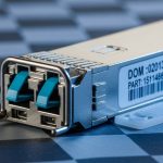
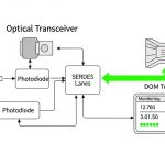
- Match DOM expectations: ensure the transceiver supports the switch’s DOM polling and that the module reports temperature and voltage in expected ranges. If your switch flags “unsupported optic,” stop and reassess.
- Stage rollout with tight monitoring: deploy to one fabric edge first, then observe error counters, link transitions, and performance during a backup window.
- Document and lock part numbers: once stable, freeze the optic part number for future spares to avoid subtle behavior changes.

Measured results: stability gains and operational impact
We applied the corrected selection and implementation plan to Fabric A first, then Fabric B after validation. During the first post-change backup window, the previously flapping ports stayed stable with zero link resets and error counters that stayed within baseline noise. Over a two-week observation period, we saw a reduction from recurring path failures to near-zero SAN path errors on the affected host clusters.
Quantitatively, before the fix the team observed multiple incidents with elevated error rates and intermittent I/O stalls, averaging roughly 2 to 5 disruptive events per day across the two edge switches during peak workload. After the corrected optics selection and connector remediation, disruptive events dropped to 0 to 1 per week, and those were traced to unrelated maintenance actions.
What changed in practice
The stability improvement came from aligning optical budget reality with switch qualification rules. The connector cleaning step mattered: a small number of links had insertion loss spikes after thermal cycling that were invisible until the system was under sustained load. DOM alignment also reduced “mystery” behavior where the switch reported generic optic health warnings despite the link appearing up.
For references, vendor datasheets and switch vendor documentation are essential. Also consult the IEEE 802.3 physical layer background for optical signaling concepts and the SFF committee for the transceiver form factor and management expectations. Sources: [Source: IEEE 802.3 Standards], [Source: SFF Committee], [Source: vendor switch datasheets and optics compatibility matrices].
Selection criteria checklist for fiber channel SFP in real SANs
When engineers choose fiber channel SFP modules, they typically work through a disciplined checklist to avoid expensive rework. Use this ordered list as a practical decision flow.
- Distance and link budget: confirm measured fiber attenuation and add patch panel loss. Ensure receiver sensitivity margin under worst-case temperature.
- Data rate and speed compatibility: match the FC generation supported by your switch port and the transceiver family. Do not assume “SFP” equals “same speed.”
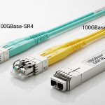
- Wavelength and fiber type: MMF commonly uses 850 nm for short reach; SMF uses other wavelengths depending on generation. Verify against the actual fiber plant.
- Connector type and polarity: LC is common, but verify polarity conventions and patch mapping. Mispatching can look like a “bad optic.”
- DOM support and switch integration: ensure the module supports diagnostics your switch can read. Mismatched DOM behavior can trigger alarms or reduce functionality.
- Operating temperature: check the transceiver temperature range and the switch’s airflow profile. A module that barely fits spec in the lab may fail in a hot aisle.
- Vendor lock-in risk: consider multi-vendor optics carefully. Third-party can be cost-effective, but only if validated by your switch platform.
Common pitfalls and troubleshooting tips
Even experienced teams run into repeatable failure modes when deploying fiber channel SFP optics. Here are the most common issues we encountered and how to resolve them quickly.
“Link up” but I/O stalls under load
Root cause: marginal optical power budget due to underestimated patch loss, dirty connectors, or aged ferrules. Under light traffic it appears fine; under sustained load it reveals CRC-like errors and retries.
Solution: inspect connectors with a fiber microscope, clean with approved tools, and re-test insertion loss on the exact affected run. If needed, replace patch cords and re-measure.
Switch reports “unsupported optic” or shows erratic health
Root cause: DOM behavior mismatch or transceiver model not qualified for that switch firmware. Some platforms enforce strict optic qualification and may bring up the link only partially.
Solution: verify the exact switch model and firmware revision. Use optics listed in the compatibility matrix, or test the candidate module in a controlled port first.
Works on one fabric but fails on the other
Root cause: patch mapping differences, polarity inversion, or one side using a different fiber type despite documentation claiming equivalence.
Solution: audit patch panels for both fabrics. Confirm wavelength/fiber type per run and perform a polarity verification at the rack. Then retest with controlled traffic patterns.
Thermal-related flaps after hours of operation
Root cause: optic temperature exceeding safe margins due to airflow blockage, high ambient in a hot aisle, or modules operating near the upper limit.
Solution: check switch fan status, airflow obstructions, and transceiver temperature telemetry. Improve airflow and, if necessary, select optics with a wider operating range or better spec margins.
Cost and ROI: OEM vs third-party fiber channel SFP
Pricing varies by FC generation, reach class, and whether the module is OEM-qualified. In many enterprise markets, a qualified fiber channel SFP module typically lands in a range of roughly $200 to $800 per unit for common generations, with higher costs for niche reach or strict qualification requirements. Third-party optics can be cheaper, often 20% to 50% less, but the ROI depends on validation time and the risk of incompatibility.
TCO is not only the purchase price. A failed optics swap can introduce downtime, engineering labor, and potential incident response costs. In our case, the extra time spent on compatibility validation and connector remediation reduced repeat work and prevented at least several disruptive events that would have required costly escalation. For spares, it is usually cheaper to stock the known-qualified part number than to “experiment” during production incidents.
FAQ: fiber channel SFP buying questions engineers ask
What is the difference between fiber channel SFP and Ethernet SFP optics?
A fiber channel SFP is designed for FC signaling requirements and switch integration expectations. Ethernet SFP optics may use similar physical form factors but are not guaranteed to work for FC because the electrical signaling, link behavior, and optics qualification rules differ. Always confirm FC generation compatibility and check the switch optics list.
Can I use generic third-party fiber channel SFP modules in production?
Often yes, but only if the module is validated for your exact switch model and firmware. The biggest risks are DOM behavior mismatches and strict optic qualification enforcement that can cause alarms or instability. Plan a staged rollout and test the module on a non-critical port before broad deployment.
How do I choose between MMF and SMF for fiber channel SFP links?
Use MMF (commonly 850 nm optics) for short reach when your plant supports it and insertion loss stays within budget. Use SMF for longer distances or where cabling standards require it. The decisive factor is measured attenuation and connector quality, not marketing reach alone.
Why do my links flap even though the transceiver “matches” the speed?
Speed matching is necessary but not sufficient. Common causes include dirty connectors, patch panel loss that exceeds the budget, polarity errors, and thermal conditions that push the module out of its safe operating range. Start by inspecting connectors and re-measuring insertion loss for the exact run.
Does DOM support matter for fiber channel SFP reliability?
DOM primarily improves observability and health monitoring. In some switch platforms, DOM fields also influence how the system reports optic status and may enforce qualification policies. If your switch expects specific DOM behavior, mismatched modules can create misleading alarms or operational restrictions.
What should I stock for spares to minimize SAN downtime?
Stock the exact qualified fiber channel SFP part numbers used in production for each speed and fiber type. Include enough units for redundancy in your most critical edge switches, and keep connector cleaning and inspection tools on hand. This reduces recovery time and avoids last-minute compatibility surprises.
If you want predictable SAN uptime, treat fiber channel SFP selection as a system engineering task: match speed and fiber type, validate switch qualification, and base reach on measured loss plus connector reality. Next, deepen your planning with fiber optic transceiver compatibility and DOM support so your next optic refresh is boring in the best way.
Author bio: I have deployed and validated FC optical links in production storage fabrics, tuning optics, firmware, and connector hygiene to eliminate intermittent path failures. My work blends field diagnostics with vendor datasheet constraints to keep storage networks fast, stable, and supportable.