When a 10G or 25G link suddenly fails at higher distance, the root cause is often not the switch port, but the optical budget and module behavior. This article helps network engineers and field technicians select, validate, and troubleshoot extended reach transceivers for practical deployments where links must stay up under temperature swings, aging optics, and fiber variability.
What “extended reach” means in IEEE and vendor terms

Engineers usually say “extended reach” when they need to exceed baseline short-reach optics, often moving from OM3/OM4 multimode to longer-reach single-mode designs. The technical constraints are defined by IEEE optical link budgets and practical module parameters like launch power, receiver sensitivity, and dispersion tolerance. In real networks, the limiting factors are fiber type, end-to-end attenuation, connector losses, and transceiver compliance with the host’s electrical interface.
Key parameters that actually bound distance
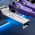
Extended reach performance is constrained by receiver sensitivity and chromatic dispersion, not by the marketing “km” number alone. For multimode, modal bandwidth and differential mode delay dominate; for single-mode, chromatic dispersion and polarization effects become more visible at higher data rates. Also confirm the module conforms to the relevant form factor and electrical standard, such as SFP/SFP+ with digital diagnostics via MSA SFF-8472 or QSFP variants with their vendor-defined management.
Common real-world references include IEEE 802.3 for optical PHY requirements and vendor datasheets for link budgets and DOM. Use these sources as your baseline: Source: IEEE 802.3 and Source: SNIA media and optics interoperability guidance.
Specifications that matter: comparing typical extended reach modules
Before purchasing, compare modules using the same measurement basis: wavelength, reach, optical power ranges, connector type, and temperature rating. Also check whether the transceiver is designed for your target fiber (SMF vs MMF) and whether it supports DOM fields your monitoring stack can ingest.
Below is a comparison of representative extended reach optics used in enterprise and data center environments. Exact values vary by vendor and part number; treat this as an engineering starting point and verify against the specific datasheet.
| Module type | Example part numbers | Wavelength | Reach (typ.) | Connector | Tx/Rx power & budget (typ.) | Operating temp | DOM |
|---|---|---|---|---|---|---|---|
| 10G extended reach (single-mode) | Cisco SFP-10G-LR, Finisar FTLX8571D3BCL | 1310 nm | 10 km | LC | ~ -9 to -3 dBm Tx, sensitivity ~ -14 dBm (varies) | 0 to 70 C (typ.) | Yes (SFF-8472) |
| 10G extended reach (single-mode) | FS.com SFP-10GSR-85 (note: short reach naming differs by SKU), Finisar variants | 1310 nm | Up to 15-20 km class depending on SKU | LC | Budget varies by exact SKU and dispersion spec | -5 to 70 C (common) | Yes |
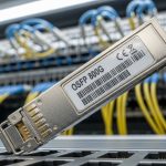
| 25G extended reach (single-mode) | Vendor QSFP28 LR / ER SKUs | 1310 nm or 1550 nm (ER) | 20 km (LR) or 40 km+ (ER) | LC | Vendor-specific; check dispersion and power | 0 to 70 C (common) | Yes (QSFP DOM) |
For authoritative electrical and optical constraints, rely on IEEE 802.3 clauses and the module vendor’s optical link budget table. For example, many LR/ER QSFP28 designs include explicit dispersion tolerance and minimum launch power requirements in their datasheets. Source: IEEE 802 task force and working group links
Pro Tip:
In field troubleshooting, engineers often find that the “distance” is not the real problem; the overlooked issue is connector and splice loss variance. Build a worst-case loss model using your actual measured OTDR results, then subtract a margin for aging and temperature effects before you blame the transceiver.
Deployment scenario: keeping 25G links stable in a leaf-spine fabric
Consider a 3-tier data center leaf-spine topology with 48-port 10G ToR switches and 100G spine links, where an expansion phase adds 25G aggregation uplinks. The network team uses extended reach transceivers on 1310 nm single-mode runs averaging 12 km, with 6 LC connectors and 2 splices per path. Measured OTDR results show connector/splice loss that ranges from 0.4 dB to 0.9 dB per path over time due to cleaning and patch panel rework.
During commissioning, they enable DOM polling every 30 seconds and set alert thresholds on received power and temperature. After 60 days, one link exhibits slowly decreasing receive power correlated with repeated patch moves; the fix is a new APC/UPC-cleaning workflow rather than swapping optics. This scenario is typical: the transceiver is “within spec,” but operational handling pushes the link budget toward the edge.
Selection criteria checklist for extended reach transceivers
Use this ordered checklist to reduce surprises during acceptance testing and future maintenance.
- Distance and real link loss: Use OTDR or at least measured attenuation including connectors and splices; do not rely on cable labeling.
- Fiber type and dispersion: Confirm SMF grade and dispersion tolerance for your data rate; extended reach at higher rates is dispersion-sensitive.
- Switch compatibility: Validate that the host supports the transceiver family and electrical signaling; some older platforms enforce stricter compliance.
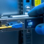
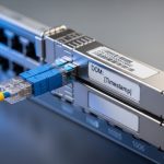
- DOM support and monitoring: Ensure DOM is readable by your NMS and that thresholds for Rx power and temperature are configured.
- Operating temperature and airflow: Compare module temperature range to your rack thermal profile; transceivers near 70 C rarely fail immediately but can drift.
- Budget and vendor lock-in risk: Check whether third-party optics are allowed by your vendor support policy and whether firmware triggers “unsupported optics” alarms.
Common pitfalls and troubleshooting tips
Extended reach transceivers usually fail in predictable ways. The goal is to separate optical power issues from configuration and physical layer problems quickly.
Pitfall 1: Assuming the advertised reach matches your fiber plant
Root cause: Link budget ignores your patch panel connectors, dirty interfaces, or extra splices added during moves. A module rated for 10 km may still fail at “12 km” if your connectors add 1–2 dB more than assumed.
Solution: Pull OTDR traces or measure end-to-end loss with a calibrated power meter. Then compute margin using worst-case attenuation and confirm Rx power remains above the module sensitivity threshold.
Pitfall 2: DOM alarms dismissed as “monitoring only”
Root cause: Some teams treat DOM warnings as non-blocking. In practice, elevated temperature or falling Rx power can precede link flaps.
Solution: Correlate DOM trends with interface errors (CRC, symbol errors, FEC counters when applicable). If Rx power trends downward, schedule cleaning and patch replacement before swapping optics.
Pitfall 3: Connector contamination at the transceiver face
Root cause: Even a small contamination on LC ends can create additional loss, especially at higher sensitivity thresholds. The result looks like “intermittent reach failures.”
Solution: Use a fiber microscope and verified cleaning procedure (dry wipe plus appropriate solvent when needed). Replace patch cords if you see scratches or persistent particulate.
Pitfall 4: Mismatch between module class and host expectations
Root cause: Some hosts enforce transceiver compatibility profiles; others accept optics but require correct speed negotiation settings. Misconfiguration can cause link instability rather than a hard link down.
Solution: Confirm port mode, speed, and FEC settings. Validate optics compatibility using the switch vendor’s supported optics list for your exact model.
Cost and ROI: what to budget for over a multi-year lifecycle
Pricing varies widely by speed and reach. As a practical range, many 10G extended reach SFP+ optics land roughly in the tens to low hundreds of dollars each, while 25G QSFP28 extended reach optics can be higher due to tighter optical and dispersion requirements. OEM optics typically cost more but may reduce support friction; third-party optics can be cost-effective if validated against your switch model and DOM tooling.
For ROI, include total cost of ownership: optics replacement rate, truck rolls for “intermittent” troubleshooting, and downtime risk during maintenance windows. In environments with frequent patching, investing in microscope-based cleaning and disciplined patch management can outperform buying “stronger” optics because it preserves link margin for the entire fleet.
FAQ
How do I verify an extended reach transceiver is compatible with my switch?
Check your switch vendor’s supported optics list for the exact switch model and port type. Then validate in a staging environment by monitoring DOM and interface error counters under sustained traffic. If you see “unsupported optics” alarms, the module may still light but can behave poorly under specific negotiation settings.
Do extended reach transceivers require single-mode fiber?
Many extended reach designs are single-mode (SMF) for higher distances and better dispersion characteristics, especially at 25G and above. However, some “extended reach” multimode variants exist for specific fiber bandwidth budgets. Always confirm by part number datasheet, not by generic reach claims.
What DOM metrics should I alert on?
At minimum, alert on received optical power, transmit power, temperature, and supply voltage if available. Set thresholds based on your baseline during commissioning, then add headroom for normal drift. If you only alert on link down events, you will miss early warning signs.
Why does my link flap after cleaning and still fail months later?
Persistent failures months later usually indicate fiber damage, repeated contamination, or added losses from re-cabling and patch changes. Use microscope inspection after any patch move and re-measure end-to-end loss if DOM Rx power trends downward over time.
Is it worth paying for OEM optics for extended reach links?
OEM optics can reduce administrative friction and may align best with vendor support expectations. Third-party optics can be cheaper, but only if you validate compatibility, DOM behavior, and optical budgets for your specific host. For safety-critical uptime requirements, run a limited pilot before scaling.
What is the fastest troubleshooting path when a link will not come up?
Start with physical layer checks: correct fiber type, polarity, and connector cleanliness using a microscope. Then confirm port speed and configuration, read DOM, and measure optical levels if you have a calibrated meter. If DOM is absent or readings are out of range, suspect an incompatible optics profile or a faulty module.
Extended reach transceivers can deliver reliable performance beyond baseline distances when optical budgets, fiber losses, and host compatibility are treated as engineering inputs rather than assumptions. If you are planning a migration, start with How to choose fiber optic transceivers for high-density data centers and align module selection with your measured link loss and monitoring strategy.
Author bio: Field-focused network architect with hands-on experience commissioning optical links in enterprise and data center environments, including DOM-based monitoring and OTDR-driven acceptance testing. Builds resilient designs by combining IEEE PHY requirements, vendor datasheets, and operational runbooks for high-availability deployments.