Ex-rated transceiver selection for oil and gas fiber links
Oil and gas operators often need fiber links that stay reliable near pumps, compressors, and tank farms where explosive atmospheres are classified. This article helps network engineers and field techs choose an Ex-rated transceiver for SFP-based fiber runs in hazardous environments, covering practical compatibility checks, environmental limits, and troubleshooting. You will also get a decision checklist, a real deployment example with numbers, and common failure modes seen in the field.
What “Ex-rated transceiver” means for SFP fiber in hazardous areas
An Ex-rated transceiver is an optical transceiver intended to be installed in a zone where explosive gas or dust may be present. In practice, engineers align the hardware with explosion protection concepts such as intrinsic safety or flameproof, and they verify that the transceiver and its interface ecosystem can be used within the certified installation constraints. For fiber networks, the optical path is electrically isolated from the hazardous environment, but the transceiver electronics still must meet the applicable certification requirements for the installation.
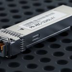
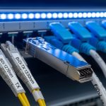
On the SFP side, the form factor is commonly the same as standard SFP, yet hazardous-area approval depends on the specific module variant, housing, sealing, and thermal behavior. A field engineer will care about the module’s allowed temperature range, power draw under load, and whether the module is designed for the host’s SFP cage constraints. When you plan an installation, treat the approval as a system claim: the module, host port, cabling, and the enclosure all affect compliance.
For standards context, explosion protection is governed by IEC equipment standards and marking schemes used across many regions, while fiber network behavior is governed by IEEE Ethernet optics requirements. For the optics side, the relevant baseline for common Ethernet rates is IEEE 802.3, and the optical performance characteristics are typically validated against vendor datasheets and lab test reports. For explosion protection, you must use the module’s own certificate and installation instructions from the manufacturer, and then map it to your site’s zone classification. IEC overview and IEEE 802.3 overview are good starting points for the underlying frameworks. [Source: IEC and IEEE public references]
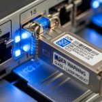
Pro Tip: In hazardous-area builds, the biggest “gotcha” is not optical reach; it is host-port power and thermal derating. Even if a module is certified, a host that drives the SFP above the module’s allowed supply window can shift temperature inside the cage and push the transceiver outside its certified operational envelope.

SFP optical basics you must align with Ex-rated constraints
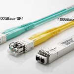
Selection starts with the Ethernet rate and the fiber type. In oil and gas networks, 1G and 10G are common for legacy upgrades and backbone aggregation, while 25G and 40G appear in newer skids. SFP (not SFP+) modules map to specific optical standards such as 1000BASE-SX/LX or 10GBASE-SR/LR depending on the module generation. You must match the transceiver to the switch or media converter port type and to the optics standard supported by the host firmware.
Then you map the optical interface to reach and fiber plant conditions. Many sites use multimode fiber (MMF) for short runs between cabinets and single-mode fiber (SMF) for longer spans across yards. In dusty or vibration-heavy areas, connectors and splices matter as much as the transceiver spec. Budget for insertion loss and connector contamination; a certified module cannot compensate for a plant that exceeds the receiver sensitivity margin.
Example spec targets for common hazardous-area Ethernet links
Below is a practical comparison table using typical parameters you will see in datasheets for SFP-class optics. Actual values vary by vendor and by whether the module is a standard SFP, an enhanced temperature module, or the hazardous-area certified variant. Always confirm the exact part number and the approved temperature band for the Ex installation.
| Parameter | 10GBASE-SR SFP+ | 10GBASE-LR SFP+ | 1GBASE-LX SFP |
|---|---|---|---|
| Typical wavelength | 850 nm | 1310 nm | 1310 nm |
| Fiber type | MMF (50/125) | SMF (9/125) | SMF (9/125) |
| Typical reach target | 300 m (MMF) | 10 km (SMF) | 5 km to 10 km |
| Connector | LC duplex | LC duplex | LC duplex |
| Operating temperature | Often -5 C to 70 C (varies) | Often -5 C to 70 C (varies) | Often -5 C to 70 C (varies) |
| Ex-rated variant availability | Common for rugged/extended temp lines | Common where longer reach is needed | Less common but available from select vendors |
| Power class (typical) | ~1.0 W class | ~1.5 W class | ~1.0 W class |
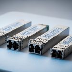
To ground the optics discussion in real products, you will often see 10G SR modules like Cisco SFP-10G-SR, Finisar FTLX8571D3BCL, or FS.com SFP-10GSR-85 on the standard side. For hazardous-area deployments, the Ex-rated versions may come from the same OEM family but with different certification, sealing, and temperature derating. Treat those standard part numbers as reach references, not as proof of hazardous-area approval. [Source: vendor datasheets such as Cisco, Finisar, and FS.com product pages]

Real deployment scenario: Ex-rated SFP in a 3-tier oil and gas network
Consider a 3-tier architecture in an offshore processing facility: access switches in control rooms connect to fiber aggregation in a central substation, then uplink to the onshore edge over SMF. You have 48-port 10G ToR switches feeding 10G uplinks to aggregation, and each hazardous zone has a sealed enclosure hosting the SFP modules. In one segment, the run is 1.2 km from a field junction cabinet to the substation; the plant uses single-mode fiber with an estimated total end-to-end loss of 4.5 dB including splices and connectors.
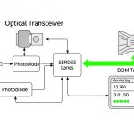
You select an Ex-rated 10GBASE-LR SFP+ (1310 nm, LC duplex) because the LR class supports the needed reach while leaving margin for aging and connector cleaning cycles. The host switch supports SFP+ optics and you verify compatibility using the switch vendor’s optics matrix and the module’s DOM support. During commissioning, a field engineer reads DOM values via SNMP: Tx power stabilizes at a target band, RX power stays above the host’s threshold, and temperature remains within the module’s allowed range. If the ambient in the sealed enclosure reaches 55 C, you confirm that the Ex-rated module’s certified temperature band still covers it with derating accounted for.
This scenario highlights why the Ex-rated transceiver choice is both optical and operational. Even when the optical budget looks healthy, the installation must remain within hazardous-area certification constraints, including thermal behavior and interface limitations. [Source: typical commissioning practices based on vendor DOM behavior and IEEE optical link budgets]

Decision checklist: choosing the right Ex-rated transceiver for your SFP cage
Engineers typically evaluate the following factors in order. If you satisfy the early items but fail later compatibility checks, you end up with intermittent link flaps or ports that refuse to bring up under load.
- Hazardous area certification fit: confirm the module’s certificate, marking, and the allowed zone and gas group/dust conditions for your site. Verify the installation instructions for any required host-enclosure conditions. [Source: manufacturer certification documents]
- Data rate and standard: match the Ethernet rate (1G/10G/25G where applicable) and the optics standard (SR vs LR). Ensure the SFP vs SFP+ form factor is correct for the host.
- Optical budget: run a link budget using your measured fiber attenuation and connector/splice losses. Use receiver sensitivity and Tx power figures from the exact module datasheet.
- Host switch compatibility: confirm the host supports the exact class of transceiver, including speed mode and whether it requires vendor-validated optics. Check the optics compatibility list for the switch model.
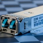
- DOM and monitoring: verify whether the Ex-rated transceiver provides Digital Optical Monitoring and whether the host reads it correctly. DOM is crucial for proactive maintenance and alarms.
- Operating temperature and derating: hazardous enclosures often run warmer than room conditions. Confirm the certified temperature band and any derating guidance for high ambient operation.
- Supply voltage and power draw: confirm the module’s allowed supply range and power class matches the host SFP cage specification. This impacts thermal stability in sealed enclosures.
- Connector and cleaning strategy: LC duplex is typical, but confirm connector polish type and plan for routine cleaning with scopes to maintain margin.
- Vendor lock-in risk: evaluate long-term spares availability, warranty terms, and whether third-party procurement is allowed without breaking compliance. Ex-rated modules may have fewer approved suppliers.
Pro Tip: If DOM alarms are enabled, configure thresholds with hysteresis based on your measured baseline, not on factory default. Field aging and enclosure heat soak shift the “normal” range, and tight thresholds can create nuisance alarms that mask real faults.
Common mistakes and troubleshooting for Ex-rated SFP optics
Below are common failure modes seen during commissioning and later operations. Each includes a likely root cause and a practical fix.
Link flaps after the first thermal cycle
Root cause: the module is used near the edge of its certified temperature band, or the host SFP cage airflow is insufficient inside the hazardous enclosure. Thermal expansion can also stress fiber connectors, especially when cables are repeatedly re-terminated.
Solution: measure enclosure ambient and internal cage temperature during peak operations, then compare to the module’s certified operating range. Improve cable strain relief, use proper connector seating, and rerun optical power checks after the enclosure reaches steady-state temperature.
“No module detected” or port stays down
Root cause: SFP vs SFP+ mismatch, unsupported optics mode, or a host compatibility limitation triggered by the module’s EEPROM identification. In hazardous-area builds, engineers sometimes swap modules during maintenance with a non-approved part that looks similar externally.
Solution: verify the host’s optics compatibility list for the exact switch model and firmware. During spares planning, lock inventory to approved Ex-rated part numbers and implement a receiving checklist that reads EEPROM/DOM identifiers before installation.
Receiver power marginal, errors increase over time
Root cause: fiber plant loss is higher than assumed, often due to dirty connectors, aged splices, or incorrect fiber type (MMF vs SMF) for the selected SR/LR class. In oil and gas sites, airborne particulates can contaminate connectors faster than in office environments.
Solution: clean and inspect connectors with a fiber scope, then measure optical power at both ends. Recompute the link budget using measured values and confirm you have sufficient margin for aging and cleaning intervals.
DOM values look “normal” but traffic is still impaired
Root cause: the optical layer may be up while higher-layer issues persist, such as CRC errors caused by a duplex mismatch elsewhere, or a host port configuration mismatch. DOM only reflects optical health, not full end-to-end Ethernet correctness.
Solution: check interface counters (CRC/FCS errors), confirm speed/duplex settings match the topology, and validate with a traffic test. If errors correlate with specific times, inspect enclosure vibration sources and connector integrity.
Cost and ROI: budgeting for Ex-rated transceivers in the field
Ex-rated transceivers typically cost more than standard commercial optics because of certification, ruggedized packaging, and limited supply. In real procurement, standard 10G SR/SFP+ modules may be relatively inexpensive, while Ex-rated variants often sit at a meaningful premium. As a planning range, many teams see Ex-rated optics priced several times higher than non-certified equivalents, with total installed cost dominated by labor, spares logistics, and downtime risk.
ROI comes from reduced downtime and fewer compliance-driven failures during audits. If you are replacing a failed module in a sealed hazardous enclosure, the cost includes technician time, isolation procedures, and potential production impact. A practical TCO model should include: module unit price, expected failure rate over the warranty window, spares carrying cost, and the cost of verification testing (optical measurement and DOM validation). For OEM vs third-party, OEM modules often align with host compatibility more reliably, while third-party options can reduce unit price but increase integration risk. [Source: typical enterprise TCO modeling practices and vendor warranty terms]
FAQ: Ex-rated transceiver questions from engineers
Do I need an Ex-rated transceiver if the fiber is non-electrical in the hazardous zone?
Yes, if the transceiver electronics are installed in the hazardous area and the host port and module assembly are part of the certified installation. While the optical path is isolated, the module still contains active electronics that must meet explosion protection requirements. Always follow the module’s certificate and installation instructions.
What is the safest way to confirm compatibility with my SFP cage?
Use the host switch or media converter optics compatibility list for your exact model and firmware version, then verify the transceiver part number. During commissioning, check link bring-up and read DOM values if supported. Avoid relying on generic “SFP is SFP” assumptions.
How do I choose between SR and LR for an oil and gas yard?
Choose based on measured fiber attenuation and the required reach, not only the transceiver reach headline. Then confirm connector and splice losses and ensure you have margin for aging and contamination. In yards with longer spans and more splices, LR on SMF often simplifies margin planning.
Can I use standard transceivers and rely on enclosure sealing for compliance?
Usually no, because certification is tied to the specific equipment and installation as defined in the module certificate. If the transceiver itself is not approved for that hazardous area, sealing does not automatically confer compliance. The correct path is to use the certified Ex-rated module variant or to relocate non-approved optics outside the hazardous zone.
What DOM metrics should I monitor after installation?
Monitor Tx optical power, Rx optical power, module temperature, and any vendor-specific alarm thresholds exposed via the host. Establish a baseline after the enclosure reaches steady-state temperature, then alert on deviations that suggest contamination, aging, or thermal stress. Treat DOM as optical telemetry, not a complete network health check.
What are the most common causes of optical link failures in the first month?
Connector contamination during installation, incorrect fiber type selection, and insufficient optical margin are frequent causes. A second set of failures comes from thermal cycling in sealed enclosures leading to marginal seating or thermal derating. Implement cleaning with fiber scope inspection and verify optical levels after thermal steady state.
If you treat the Ex-rated transceiver as a certified system component and validate it with optics budgeting, host compatibility checks, and DOM-based monitoring, you reduce both compliance risk and operational downtime. Next, review oil gas fiber optics SFP for field-ready practices on cabling, cleaning, and commissioning workflows in industrial environments.
Author bio: I have worked hands-on with fiber optic deployments in industrial control rooms, including hazardous-area switch cabinets and DOM-driven maintenance workflows. I write from field experience balancing IEEE optics behavior, vendor compatibility constraints, and practical commissioning limits.