Energy harvesting sensor networks live on a narrow power budget, yet they still need reliable links for telemetry, firmware updates, and time sync. This article helps field engineers and IT directors choose and deploy an IoT sensor SFP that fits low-power optics, specific fiber distances, and the governance constraints of real networks. You will walk away with a step-by-step implementation plan, a compatibility checklist, and troubleshooting patterns from deployments in outdoor substations and campus microgrids.
Prerequisites: align optics, power, and enterprise governance
Before you touch a module, confirm that the access layer design can sustain optical power, link budget, and operational temperature across the sensor site. Plan for both physical governance (asset tagging, spares, lifecycle) and architectural governance (standard optics profiles, DOM telemetry collection, and change control). This reduces downtime when a sensor node needs field replacement after a storm or a connector corrosion event.
Define the network physics and the sensor power envelope
Write down the expected link distance, fiber type, and environment. For energy harvesting sites, also note the duty cycle: for example, a node that wakes every 60 s and transmits for 200 ms reduces average power draw but still requires link establishment margins. Use the IEEE 802.3 relevant clauses for Ethernet PHY behavior and vendor datasheets for optical power and receiver sensitivity; see [Source: IEEE 802.3].
Expected outcome: a one-page link budget and a power budget that justify selecting multimode vs single-mode optics and the data rate class.
Establish the “optics standard” for your fleet
In enterprise environments, you want repeatable optics behavior across access switches. Choose a policy: “Only SFP modules with verified DOM support and known vendor compatibility are allowed for IoT sensor SFP deployments.” Then require that the switch can read DOM values and log thresholds. This governance step prevents silent drift when third-party modules behave differently under temperature swings.
Expected outcome: an approved module list and a documented compatibility matrix for your switch models.

Step-by-step deployment: selecting an IoT sensor SFP that survives the field
In energy harvesting networks, the optics choice is not just distance and bandwidth; it is also about connector reliability, temperature rating, and the ability to detect failing links early through DOM telemetry. The goal is to keep the sensor link stable during cold starts, humidity cycling, and low-power wake windows.
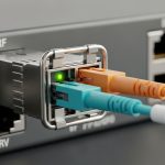
Pick the optical profile by distance and fiber type
For short runs inside enclosures or campus microgrids, multimode is often cost-effective. For longer outdoor spans, single-mode is usually mandatory. Common field-friendly choices include 10GBASE-SR over multimode and 10GBASE-LR or 10GBASE-ER over single-mode, depending on your link length and split losses; validate against the exact fiber plant and connector loss.
Validate switch compatibility and DOM behavior
Many enterprise switches expect specific SFP electrical characteristics and will still pass link even when DOM is absent, which is dangerous for remote maintenance. Prefer modules that support Digital Optical Monitoring (DOM) so you can alert on Tx power, Rx power, and temperature. When feasible, test in staging by reading DOM values via the switch CLI and forcing a controlled temperature change.
Expected outcome: a verified “plug and monitor” path, not only a “plug and hope” path.
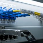
Install with connector governance and strain relief
Outdoor energy sites punish poor termination. Use proper fiber management, clean connectors before mating, and apply strain relief that prevents micro-bending during wind gusts. For governance, require that field techs attach an asset tag, record serial numbers, and log DOM baseline values at installation time.
Expected outcome: traceable optics assets with baseline telemetry for future incident response.

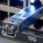
Specs that matter: a practical comparison for IoT sensor SFP choices
Use the table below to narrow module options quickly. Even when data rates match, wavelength, connector type, and temperature range can make or break a sensor deployment.
| Module type (examples) | Wavelength | Reach (typical) | Fiber | Connector | Data rate | Power / DOM | Temperature range |
|---|---|---|---|---|---|---|---|
| Cisco SFP-10G-SR | 850 nm | Up to ~300 m (MM) | OM3/OM4 multimode | LC | 10G | DOM supported (vendor spec dependent) | Commercial/extended (verify exact SKU) |
| Finisar FTLX8571D3BCL | 850 nm | ~300 m (MM) | OM3/OM4 multimode | LC | 10G | DOM supported | Industrial/extended (verify datasheet) |
| FS.com SFP-10GSR-85 | 850 nm | ~300 m (MM) | OM3/OM4 multimode | LC | 10G | DOM supported (commonly) | Commercial/industrial (verify listing) |
| Single-mode alternative (10GBASE-LR class) | 1310 nm | ~10 km (SM typical) | OS2 single-mode | LC | 10G | DOM supported (varies) | Industrial recommended for outdoors |
Note: Always confirm exact reach using your measured link loss and the module vendor’s link budget guidance. References: [Source: IEEE 802.3], and individual module datasheets from the cited vendors.
Pro Tip: In field conditions, DOM alarms on temperature often precede optical power degradation by days. Configure switch thresholds so you receive alerts before the sensor node misses its next wake window, then replace optics proactively rather than reactively.

Selection criteria checklist: the order engineers actually use
- Distance and fiber type: choose SR for short MM runs, LR/ER class for longer SM spans; verify with measured attenuation and connector loss.
- Switch compatibility: confirm the SFP is supported by the exact switch model and firmware; test DOM readout.
- DOM support and alerting: require Tx/Rx power and temperature telemetry; set thresholds and log history.
- Operating temperature: prefer industrial/extended modules for outdoor enclosures with thermal cycling.
- Connector and cleaning practicality: LC cleanliness and proper strain relief matter more than marginal reach.
- Budget and vendor lock-in risk: compare OEM vs third-party TCO; ensure spares availability and consistent behavior.
- Governance and lifecycle: record serial numbers, enforce change control, and standardize approved part numbers.
Common mistakes and troubleshooting: three failure modes you can prevent
Failure mode 1: “Link up” but sensors intermittently miss packets
Root cause: marginal optical power due to dirty connectors or higher-than-modeled splice/patch loss; the link may negotiate but errors spike during wake windows. Solution: clean connectors, inspect with a fiber scope, re-measure loss, and check DOM Rx power trends for a downward drift.
Failure mode 2: SFP works on one switch, fails on another
Root cause: electrical compatibility and vendor-specific implementation of SFP requirements; some switches enforce stricter control signals or refuse DOM. Solution: validate against the switch model and firmware; if needed, standardize on OEM optics for that fleet segment.
Failure mode 3: Frequent resets after cold start
Root cause: temperature ramp delays and insufficient thermal tolerance; transceiver temperature may lag during enclosure cool-down, causing timeouts. Solution: select an industrial-rated IoT sensor SFP, improve enclosure thermal design, and confirm that the module’s temperature range matches your site extremes.
Cost and ROI note: what you save, what you risk
OEM transceivers often price higher, commonly in the range of $80 to $200 per unit depending on reach and temperature grade. Third-party modules may be 20% to 50% cheaper, but ROI depends on your downtime cost and the ability to monitor DOM reliably. In energy harvesting networks, the real cost is not only the module price; it is lost telemetry windows, truck rolls, and extended outage durations when a sensor node becomes unreachable during its low-power sleep cycle. Treat TCO as: transceiver cost plus installation labor plus failure rate plus mean time to recovery, and prioritize modules that reduce unknowns.
FAQ: IoT sensor SFP for energy harvesting deployments
Which data rate should I choose for an IoT sensor SFP?
Most energy harvesting deployments start with 1G or 10G depending on backhaul density. If you aggregate many sensors per node, 10G can reduce congestion and retransmits, but it may increase power at the edge. Align with your switch power profile and duty cycle requirements.
Can I use third-party optics in a managed enterprise network?
Yes, but only after you validate compatibility and DOM behavior on the exact switch models. Governance matters: standardize approved part numbers, test in staging, and log DOM baselines so you can detect drift across vendors.
What fiber type is best for remote sensor enclosures?
For short runs, multimode with LC connectors is often economical. For outdoor or longer spans, single-mode is usually safer because it tolerates longer distance budgets and supports stable link performance with lower attenuation over distance.
How do I monitor link health when sensors sleep frequently?
Rely on DOM telemetry from the switch-facing side: watch Tx power, Rx power, and temperature. Configure alerts so you receive warnings even when the sensor node is asleep, then repair before the next wake window.
What is the most common cause of intermittent link errors outdoors?
Connector contamination and micro-bending are