Edge computing deployments fail in frustratingly repeatable ways: link flaps that look like “random” packet loss, optics that pass diagnostics but still misbehave, and fiber plants that degrade only under temperature swings. This guide helps network engineers and field technicians troubleshoot optical link issues end-to-end, from transceiver parameters to fiber continuity and switch-side compatibility checks. You will get a practical decision checklist, a comparison table of common transceiver types, and concrete failure modes with root causes and fixes.
Start with link symptoms: map failures to likely optical causes

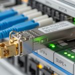
Before you touch fiber, classify the symptom you see on the edge switch ports. In practice, the fastest triage comes from correlating: interface state (down, err-disabled, up but flapping), optical diagnostics (DOM/Tx power/Rx power/bias current/temperature), and error counters (FCS, CRC, alignment, loss-of-signal). IEEE 802.3 PHYs expose consistent patterns: a receive-side signal problem often yields loss-of-signal or very low Rx power; a transmitter or lane problem can show high BER-adjacent errors even when link comes up.
Field triage workflow (5 to 12 minutes)
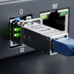
- Confirm the exact port and speed: capture the negotiated rate (example: 10GBASE-SR vs 1000BASE-SX) and admin settings (forward error correction, auto-negotiation behavior if applicable).
- Pull DOM telemetry from the switch/OS: Tx power, Rx power, bias current, temperature, and vendor part/serial if available.
- Check counters over 60 to 120 seconds: CRC/FCS increments, symbol errors, and any “link training” related events.
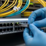
- Swap optics across known-good ports: if your optics are replaceable, move the same transceiver to a different port with similar configuration.
- Only then inspect fiber: clean, re-seat, and test continuity and optical power end-to-end.
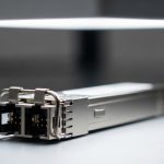
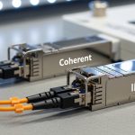
Know your transceivers: SR vs LR vs active optics and what DOM should look like
Edge computing optical links typically use short-reach multimode (SR) in cabinets and data rooms, or single-mode (LR/ER/ZR) when the fiber run crosses outdoor segments or long hallways. Troubleshooting gets easier when you know what “normal” looks like for your specific optic family and wavelength. Vendor datasheets usually specify acceptable Tx power and Rx sensitivity ranges, but real deployments also include aging optics, connector contamination, and temperature drift.
Quick spec comparison (common module families)
| Transceiver type | Wavelength | Typical reach | Fiber type | Connector | Power/diagnostics | Operating temperature |
|---|---|---|---|---|---|---|
| 10G SFP+ SR (example: Cisco SFP-10G-SR) | 850 nm | ~300 m on OM3 / ~400 m on OM4 (varies by vendor) | Multimode | LC | DOM: Tx/Rx power, bias current, temperature | Often commercial 0 to 70 C or extended depending on part |
| 10G SFP+ LR (example: Finisar FTLX8571D3BCL) | 1310 nm | ~10 km | Single-mode | LC | DOM: Tx/Rx power, bias current, temperature | Commonly -5 to 70 C (check datasheet) |
| 25G SFP28 SR (example: FS.com SFP-25G-SR) | 850 nm | ~100 m (varies by OM and coding) | Multimode | LC | DOM supported; higher lane sensitivity than 10G | Commercial/extended variants exist |
| 100G QSFP28 SR4 (example family) | 850 nm | ~100 m (OM4 typical) | Multimode | LC (4-lane) | DOM per lane; more failure modes from one bad lane | Varies by model |
Practical DOM interpretation: if the link is down with very low Rx power (or reported “loss of signal”), suspect fiber breaks, wrong fiber type, or an unclean connector. If the link is up but CRC/FCS errors spike, suspect marginal receive power, mis-matched optic types, or a single-lane impairment (especially on multi-lane optics like QSFP28 SR4). Always compare Tx and Rx values to the vendor’s “typical” and “minimum/maximum” thresholds; vendors publish them in the transceiver datasheet and in compliance docs aligned with IEEE 802.3.
Pro Tip: In multi-lane optics (QSFP28 SR4 or higher), a single contaminated connector on one lane can keep the link “up” while CRC errors climb. Check per-lane DOM (if exposed) and then clean and re-seat the exact LC pair tied to that lane—do not assume the problem is global to the whole module.
Fiber and connectors: the most common root cause in edge sites
In edge computing cabinets, fiber problems cluster around connector cleanliness, re-seat cycles, and micro-bends from constrained routing. Even when the fiber passes continuity tests, optical loss can still be high enough to push the receiver into an error regime. For multimode SR links, connector contamination and fiber plant loss are amplified by higher aggregate bandwidth and stricter signal-to-noise requirements.
What to test in the field (in order)
- Physical inspection: verify connector polarity and that fibers are not swapped (Tx/Rx cross for duplex links).
- Clean before you measure: use a proper optical cleaning method (cassette or swab designed for LC/SC/MT ferrules) and re-check.
- Continuity and end-to-end mapping: confirm you are testing the same fiber pair you think you are.
- Optical power measurement: use a calibrated light source and power meter (or an OTDR where appropriate) to validate expected attenuation.
- Check for micro-bends: inspect bend radius near patch panels and trays; replace suspect jumpers.
Selection criteria: how to pick optics that will survive real edge conditions
Edge computing sites introduce operational variability: vibration, temperature cycling, limited maintenance windows, and sometimes “mixed vendor” optics during spares swaps. A robust selection process reduces future troubleshooting time and lowers mean time to repair (MTTR). Use the checklist below during procurement and during spares planning.
Decision checklist engineers actually use
- Distance and link budget: verify your run length and connector/fiber loss using measured values, not just labeled distances.
- Wavelength and fiber type: confirm 850 nm multimode vs 1310 nm/1550 nm single-mode alignment with the installed plant.
- Switch compatibility: check the switch vendor’s transceiver compatibility list and transceiver type requirements (SFP+/SFP28/QSFP28; SR vs LR).
- DOM support and telemetry quality: ensure DOM is readable over the management plane and that you can access Tx/Rx power and temperature.
- Operating temperature and derating: confirm the optic supports the cabinet ambient range, including sunlight/airflow extremes.
- Vendor lock-in risk: decide whether OEM-only optics are required or whether third-party optics meet the same thresholds for Tx/Rx power and DOM.
- Connector type and mating hardware: ensure LC/SC/MT ferrule type matches your patch panels and that cages provide correct retention force.
- Planned maintenance pattern: if you expect frequent swaps, prioritize optics with stable DOM and known-good aging characteristics.
Authority note: transceiver behavior and link expectations are governed by IEEE 802.3 physical layer specifications for Ethernet over fiber, and optics compliance is typically validated against the relevant IEEE electrical/optical requirements. For example, IEEE 802.3 defines optical PHY characteristics and interface expectations for 10G/25G/100G families. IEEE 802.3 standard portal and vendor datasheets (e.g., Cisco and Finisar/II-VI) provide the concrete DOM and optical power ranges. Cisco SFP module datasheet examples
Common mistakes and troubleshooting tips (root cause and fix)
Most edge optical failures come from a small set of patterns. Use this list to avoid wasted cycles and to converge quickly when you are on-site with limited tooling.
Link down with loss-of-signal, but continuity “passes”
Root cause: connector contamination or wrong fiber pair mapping. Continuity testers can still show continuity even when optical loss is too high for the receiver.
Fix: clean both ends, verify duplex polarity, and measure optical power with a light source/power meter. Re-seat the transceivers and re-check DOM Rx power.
Link up but CRC/FCS errors spike after thermal changes
Root cause: marginal optical budget or temperature-driven power drift; the link is “just barely” meeting sensitivity at one temperature but fails at another.
Fix: compare measured Rx power to datasheet sensitivity under your wavelength and code rate; shorten the patch path or replace jumpers; validate connector loss with OTDR if available.
Works on one port but fails on another
Root cause: switch port optics support mismatch, incompatible transceiver type, or a port-level cage/firmware quirk. Some platforms accept only specific DOM reporting formats or require certain optic profiles.
Fix: swap optics into the known-good port; if failure follows the port, inspect the cage, update switch firmware, and consult the transceiver compatibility list. If failure follows the optic, replace with a compatible module.
Multi-lane errors on QSFP28 SR4: one lane silently degrades
Root cause: one contaminated LC pair or a damaged fiber in only one lane. The link may remain up while error counters climb.
Fix: check per-lane DOM (if exposed), then clean and re-seat the specific LC connectors and test the corresponding fiber pair.
Cost and ROI note: minimize MTTR without overpaying
In edge computing, the cost of downtime often dwarfs the optics BOM. Typical street prices (highly variable by region and contract) for 10G SFP+ optics often range roughly from $30 to $200 for common SR/LR variants, while 25G/100G optics can be higher (often $150 to $1000+ depending on reach and coding). OEM optics can reduce compatibility risk, but third-party optics can be cost-effective if they meet the same DOM and optical power thresholds and are validated on your switch models.
TCO drivers: expected failure rate (especially from connector contamination and field re-seat cycles), labor time for cleaning and testing, and the time cost of troubleshooting. A practical ROI move is to standardize a small set of optic models per edge site type and keep verified spares; it reduces configuration drift and speeds up “swap test” triage.
FAQ
How do I tell if the problem is the fiber plant versus the optic?
Use a controlled swap test: move the same optic to a known-good port and move a known-good optic to the suspect port. If DOM Rx power and counters follow the optic, suspect the module; if they follow the port/fiber path, suspect the cage or fiber.
What DOM values matter most during edge computing link failures?
Tx power, Rx power, bias current, and temperature. When the link is down, Rx power and loss-of-signal indicators are the fastest signal; when the link is up but errors rise, compare Rx power stability and watch for temperature-driven drift.
Can continuity testing replace optical power measurement?
No. Continuity checks can pass even when insertion loss is high due to contamination or micro-bends. For reliable diagnosis, measure optical power with a calibrated light source and power meter, and use OTDR when you need location of loss.
Are third-party optics safe to use in edge environments?
They can be, but only after validating compatibility with your exact switch model and confirming DOM behavior and optical power thresholds match your expected link budget. If your platform has strict optic verification, OEM modules may be necessary.
Why do I see link flaps only under heavy temperature or sunlight exposure?
Optics can drift with temperature, and connector contamination can worsen as thermal expansion changes contact conditions. Validate operating temperature range, check for marginal Rx power, and inspect fiber routing for micro-bends that become active under cabinet airflow changes.
Which standards should I cite in an incident report?
Reference IEEE 802.3 for PHY expectations and the vendor datasheets for Rx sensitivity and DOM thresholds. Include measured Tx/Rx power, temperature, and the exact optic part numbers used during the incident.
Update date: 2026-04-30. If you want to reduce repeat incidents, the next step is to standardize optic and fiber validation procedures per edge site type using edge computing optical link budget and validation.
Author bio: I build and field-test edge networking links end-to-end, including DOM-driven diagnostics and fiber loss validation under real cabinet thermal cycles. I focus on PMF for operational reliability: repeatable triage, measurable thresholds, and MTTR reduction through disciplined standardization.