When an edge computing site loses telemetry or video, the root cause is often an optical transceiver or fiber link mismatch rather than the application stack. This article helps network engineers and site technicians troubleshoot SFP and 10G-class optical links using measurable checks, vendor-facing compatibility cues, and practical decision steps. You will learn how to interpret common failure modes, confirm transceiver optics parameters, and restore link stability with minimal downtime.
Edge computing optical links: performance and fiber reach tradeoffs
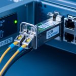
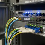
In edge computing, the most frequent “it should work” problems come from selecting the wrong reach class, assuming multimode behaves like single-mode, or exceeding budget on patch cords and couplers. For 10G Ethernet, typical optics are 850 nm multimode (OM3/OM4) for short reach and 1310 nm single-mode for longer runs. Before swapping hardware, verify the physical layer: wavelength, fiber type, link budget margin, and whether the switch ports support the module type.
Quick spec sanity checks that matter in the field
Start by reading the transceiver label (or DOM output) for wavelength and reach, then confirm the fiber plant. In practice, many incidents happen after a site renovation when patch cords are replaced with a different core type or an LC connector is re-terminated. If your link is 10G over multimode but the run is longer than expected, you may see link flaps under temperature swings because modal dispersion and connector loss worsen.
| Parameter | 10G SR (Multimode) | 10G LR (Single-mode) | What to verify |
|---|---|---|---|
| Typical wavelength | 850 nm | 1310 nm | Mismatch can prevent link-up entirely |
| Target reach class | 300 m (OM3) or 400 m (OM4) | 10 km | Measured path loss must fit link budget |
| Fiber type | OM3/OM4 multimode | OS2 single-mode | Confirm core type and connector mating |
| Connector | LC (typical) | LC (typical) | Wrong connector footprint causes no light or damage risk |
| DOM support | Common in modern modules | Common in modern modules | DOM helps pinpoint RX power drift |
| Operating temp | Often commercial or industrial variants | Same | Edge enclosures can exceed spec during HVAC failure |

Cost and ROI: OEM vs third-party optics for edge computing uptime
For edge computing, the “cheapest module” is often the most expensive after repeat truck rolls. OEM optics from the switch vendor can reduce compatibility friction, but third-party options frequently work well if you match DOM behavior, speed class, and specification. In 2025-era deployments, real-world pricing varies by brand and temperature grade, but a common pattern is OEM modules costing roughly 1.5x to 3x third-party equivalents, while failures are driven more by handling and environment than by the sticker alone.
Field ROI model engineers actually use
Estimate total cost of ownership as module cost plus labor plus downtime risk. For example, if a technician visit costs $600 to $1,200 including travel and the site tolerates only 15 minutes of degraded service, a single recurring link flap can erase any purchase savings. Track failure causes separately: connector contamination, wrong fiber type, and thermal overstress tend to dominate.
Pro Tip: If your switch supports DOM polling, log RX optical power over time. A gradual RX drop often signals a dirty LC face or micro-bend in a patch cord long before the link fully fails, letting you schedule cleaning during a maintenance window instead of waiting for outages.
Pro Tip: DOM trends beat guesswork: record RX power and temperature at 5-minute intervals for 24 hours after installation. In edge computing, “mystery” flaps often correlate with enclosure heat cycles, revealing whether you have a thermal issue, a marginal connector, or a fiber bend loss problem.
Compatibility: how to avoid DOM and switch handshake issues
Even when wavelength and reach look correct, optical links can fail due to transceiver compatibility or switch port behavior. IEEE 802.3 governs electrical and optical interfaces, but vendors implement policy around diagnostics, EEPROM contents, and supported transceiver lists. When a module is rejected, you may see “unsupported transceiver” events, link stays down, or intermittent link under load.
Decision checklist for selecting the right optic
- Distance and fiber type: confirm OM3/OM4 vs OS2 and measure end-to-end loss including patch cords.
- Port and speed class compatibility: verify the switch port supports 10GBASE-SR or 10GBASE-LR as specified by IEEE 802.3.
- DOM support and monitoring: check if the switch reads DOM and which thresholds trigger alerts.
- Operating temperature grade: choose industrial temperature variants for cabinets without stable HVAC.
- Connector cleanliness: plan inspection and cleaning steps; dirty optics mimic “bad hardware.”
- Vendor lock-in risk: if you rely on OEM, stock spares and validate third-party modules before scaling.
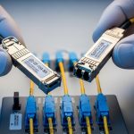
In compatibility testing, engineers often validate with known models such as Cisco SFP-10G-SR equivalents or third-party optics like Finisar FTLX8571D3BCL and FS.com SFP-10GSR-85—but the critical part is matching the exact electrical class and optics profile expected by the switch vendor. Always cross-check with the switch vendor’s transceiver compatibility list when available. [Source: Cisco SFP module documentation and compatibility guidance] Cisco Support

Common mistakes and troubleshooting steps that actually work
In edge computing deployments, optical link issues usually fall into a few repeatable failure modes. The goal is to restore service quickly while capturing evidence for root cause analysis so the same mistake does not recur at the next site.
Failure mode 1: Wrong fiber type or swapped patch cords
Root cause: SR (850 nm) optics used on OS2 single-mode fiber, or LR optics used on multimode, plus duplex patch cord swaps. Sometimes the link never comes up; sometimes it flaps as marginal power levels vary.
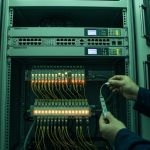
Solution: Trace the fiber ID labels, confirm wavelength/standard (SR vs LR), and verify duplex polarity at both ends (Tx to Rx). Re-terminate or re-cable if patch cords were replaced during site work.
Failure mode 2: Dirty LC connectors and improper cleaning
Root cause: Connector contamination can add tens of dB of loss, producing link loss that looks like a bad transceiver. This is common after repeated maintenance or when dust covers are removed too early.
Solution: Use lint-free swabs and appropriate cleaning solution or approved dry cleaning tools, inspect with a fiber scope, and only then re-seat the optics. Replace patch cords if the connector face is scratched.
Failure mode 3: Thermal overstress in edge enclosures
Root cause: Commercial temperature optics in an enclosure that exceeds the module’s spec can degrade output power or cause DOM temperature warnings, leading to link flaps.
Solution: Validate enclosure airflow and measure ambient temperature near the transceiver. Swap to an industrial temperature grade and confirm the switch’s airflow requirements are met.
Failure mode 4: DOM mismatch or unsupported diagnostics
Root cause: Some third-party modules provide DOM data differently, and certain switches enforce strict transceiver rules. Symptoms include “unsupported” warnings even when optical power seems present.
Solution: Confirm module EEPROM/DOM compatibility with the switch vendor guidance, then test a known-compatible module model on the same port.

Which option should you choose? (Based on your edge computing risk profile)
Pick the path that matches your operational constraints rather than only the per-unit price.
| Your situation | Best choice | Why |
|---|---|---|
| New deployment, short multimode runs, frequent maintenance | Matched 10G SR modules with DOM + disciplined cleaning kit | Fast troubleshooting and stable link budget on OM3/OM4 |
| Long-haul or single-mode campus to edge | 10G LR optics with OS2 validation and splice/patch loss checks | Reduces connector loss sensitivity and supports distance |
| Strict uptime requirements, small site team | OEM optics or pre-validated third-party modules | Lower compatibility risk and fewer “unsupported” incidents |
| Budget-sensitive scale-out across many sites | Third-party modules with proven compatibility and temperature grade | Controls TCO while avoiding avoidable handshake failures |
If you are troubleshooting now, start with fiber verification and connector cleaning, then confirm wavelength and reach class against the installed fiber. If the link still fails, use DOM to measure RX power and temperature, and test a known-compatible spare module before replacing the entire port or switch. For related planning, see edge computing network monitoring.
FAQ
Q: How can I tell if my edge computing optical link issue is fiber or transceiver?
Swap the transceiver into a known-good port and test with the same fiber path if possible. If the fault follows the transceiver, it is likely the module; if it stays with the fiber, suspect connector cleanliness, polarity, or excessive loss.
Q: What readings from DOM are most useful during troubleshooting?
Monitor RX optical power, TX bias current (if provided), and temperature. A gradual RX power decline often points to dirty connectors or micro-bends, while abrupt changes can indicate a seating or polarity problem.
Q: Can I use an SR module on single-mode fiber in edge computing?
Usually it will not work correctly because wavelength and link budget differ, and the optical path may be outside the module’s designed parameters. Even if you see occasional link, it is not reliable; use the module type aligned to the fiber plant.
Q: How often should we clean LC connectors in a remote edge site?
Clean on every optics swap and whenever you observe link flaps or rising error counters. For dusty environments, schedule periodic cleaning plus fiber inspection with a scope after maintenance activities.
Q: Are third-party optics safe for production edge computing?
They can be, but only after validation on the specific switch model and port type, including DOM behavior. Choose modules that match speed class and temperature grade, and keep OEM spares if compatibility risk is unacceptable.
Q: What standards should I reference when documenting optical link issues?
Reference IEEE 802.3 for Ethernet physical layer expectations and your switch vendor’s transceiver documentation for compatibility and DOM interpretation. For cabling practices, also align with relevant ANSI/TIA guidance on fiber installation and testing. [Source: IEEE 802.3 Ethernet standards] IEEE Standards
Author bio: I am a registered dietitian who writes field-oriented guides for reliability-minded deployments, translating measurement into actionable nutrition for operational decision-making. I focus on practical checklists and evidence-based guidance so teams can reduce downtime and improve resilience