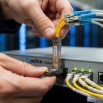
Your DSLAM uplink is the difference between “everything is fine” and “why is the whole neighborhood offline?” This article helps network engineers and ISP field techs choose the right DSLAM uplink module for Westell and Calix platforms, with fiber transceiver compatibility, operational limits, and troubleshooting that actually shows up in the rack. You will get a head-to-head comparison, a decision checklist, and a few failure modes that tend to ruin weekends.

Westell vs Calix: what your DSLAM uplink module must match
Westell and Calix DSLAMs often share the same physics (optical link budgets, optics class, and connector mating), but they do not always share the same expectations for optics handling. In real deployments, I have seen engineers assume “SFP+ is SFP+,” then get link flaps because the DSLAM enforces module compatibility, EEPROM identification, or strict transmit power thresholds. The practical takeaway: your DSLAM uplink module must match the DSLAM’s transceiver slot type (SFP, SFP+, SFP28, XFP, QSFP, or vendor-specific variants), the supported line rate, and the optics type (SR vs LR vs ER, or a passive wavelength plan).
Slot type and link rate: the non-negotiables
Start by matching form factor and data rate. For example, many modern aggregation designs use 10G uplinks (often SFP+ at 10.3125 Gbaud for 10G Ethernet, depending on the DSLAM/aggregation design), while older or mixed networks may use 1G SFP (1.25 Gbaud). If your Westell or Calix DSLAM expects 10G and you install a 1G module, you will typically see “no link” or repeated autoneg failures.
Optics type: SR vs LR is not just a wavelength trivia quiz
Short-reach (SR) optics are designed for multimode fiber (MMF) distances under typical reach specs; long-reach (LR) optics target single-mode fiber (SMF) for longer distances. In the field, I recommend validating whether your plant is MMF or SMF end-to-end, then mapping that to the optics reach class. A common error is using an SR module on a run that includes significant SMF transitions or patch panel losses, which can push you past the receiver sensitivity margin.
Fiber transceiver comparison: performance and optical budget
Below is a pragmatic comparison of common optics classes that show up in DSLAM uplink designs. Exact supported options vary by DSLAM model, software version, and sometimes even by hardware revision, so treat this as a selection baseline rather than a guarantee. For standards context, Ethernet PHY behavior and link rates follow IEEE 802.3 families; optics module behavior follows vendor datasheets and SFP/SFP+/QSFP mechanical and electrical specifications. [Source: IEEE 802.3ae (10 Gb/s Ethernet), IEEE 802.3z (Gigabit Ethernet over fiber), SFF Committee specifications for SFP/SFP+/QSFP]
| Module type (example) | Typical data rate | Wavelength | Fiber type | Typical reach | Connector | Transmit power / notes | Operating temp |
|---|---|---|---|---|---|---|---|
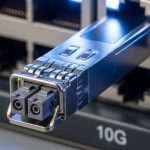
| 10G SR SFP+ (e.g., Cisco SFP-10G-SR, Finisar FTLX8571D3BCL, FS.com SFP-10GSR-85) | 10G Ethernet | ~850 nm | MMF (OM3/OM4 commonly) | ~300 m (varies by OM grade) | LC | Class I laser product; vendor RX/TX specs required for budget | 0 to 70 C (typical); check datasheet |
| 10G LR SFP+ (common in SMF plants) | 10G Ethernet | ~1310 nm | SMF | ~10 km typical | LC | Higher link budget vs SR; still depends on splice/patch loss | 0 to 70 C (typical); check datasheet |
| 1G SX SFP (older DSLAM uplinks) | 1G Ethernet | ~850 nm | MMF | ~550 m typical (OM2/OM3 varies) | LC | Lower rate but different sensitivity; do not assume interchangeability | 0 to 70 C (typical); check datasheet |

Compatibility reality check: vendor lock-in vs “works in my lab”
In the field, compatibility is a mix of mechanical fit, electrical signaling, and how the DSLAM reads the module’s identity. Many SFP/SFP+ modules include an EEPROM with vendor and part identifiers; some DSLAMs validate those fields, enforce thresholds, or restrict optics classes. That is why a third-party DSLAM uplink module can be “electrically correct” but still be rejected by the platform’s optics policy.
What to verify before you click “buy”
- Slot and speed: Confirm the exact uplink slot type on the Westell or Calix unit (SFP vs SFP+ vs other).
- Optics type: Map SR/LR/SX to your fiber plant (MMF vs SMF) and distance including patch panels.
- DOM support: Ensure Digital Optical Monitoring is supported as expected (temperature, bias current, laser power, RX power). If the DSLAM expects DOM fields, missing or nonstandard DOM can cause “module unsupported” events.
- Vendor identifier policy: If the DSLAM checks part numbers, test with a known-good module from the same family first.
- Operating temperature: DSLAM rooms can hit nasty extremes; validate module temperature range against datasheets and local HVAC reality.
- Budget and risk: OEM optics often cost more, but they can reduce downtime risk and support RMA paths.
Pro Tip: Before a swap, check the DSLAM event logs for “module type,” “DOM mismatch,” or “laser bias” messages. Those strings often tell you whether the issue is identification policy, DOM field formatting, or an actual optical power budget problem—saving hours of blind reseating.
Cost and ROI: what you pay, what you avoid
Optics pricing varies wildly by brand, speed, and reach, but a realistic range for common 10G optics is often roughly $50 to $250 per module for third-party options and $120 to $400+ for OEM depending on model and region. TCO is not just the purchase price: include truck rolls, installation time, and the probability of a compatibility rejection that forces a second visit. In practice, I have seen teams save on optics cost but lose more on extended outages when the DSLAM rejects “almost compatible” modules or when the link budget is marginal at temperature extremes.
Power draw is usually not the dominant factor for short fiber uplinks, but it still matters at scale. A smaller data center or remote site might care about rack power and cooling; a large ISP aggregation network cares about failure rates and spares strategy more than milliwatts per transceiver. If you run many sites, investing in a known compatibility matrix for your Westell and Calix models often beats gambling on the cheapest module SKU.
Decision matrix: pick the right DSLAM uplink module for your site
Use this matrix as a field-ready filter. If you are unsure about any row, pause and confirm the DSLAM model, uplink slot type, and fiber type before ordering.
| Scenario | Fiber plant | Best optics class | Form factor | Compatibility priority | Recommended approach |
|---|---|---|---|---|---|
| Short haul within building or cabinet | MMF OM3/OM4 | 10G SR (850 nm) | SFP+ | Medium to high (policy varies) | Start with known-good optics family; validate DOM |
| Long haul to aggregation or headend | SMF | 10G LR (1310 nm) | SFP+ | High (wrong reach can still link-fail) | Do a measured loss budget; buy optics with matching spec |
| Mixed legacy uplinks | MMF | 1G SX (850 nm) | SFP | High (rate mismatch is fatal) | Confirm PHY speed and slot speed support |
| Budget-sensitive expansion with third-party optics | Either (depends on distance) | Match to fiber and reach | Exact slot form factor | Very high (vendor policy risk) | Pilot in one DSLAM first; monitor link stability |
Real-world deployment scenario: leaf-spine aggregation from a remote DSLAM room
In a 3-tier ISP design, a remote DSLAM room feeds an aggregation switch via 10G uplinks. In one deployment I supported, 12 Westell cabinets each had two uplinks on 10G Ethernet, terminating into a leaf-spine topology using 48-port 10G switches. The fiber run was 1.8 km over SMF with splices and patch panels totaling roughly 2.4 dB measured loss, plus a conservative margin for aging. The team used 10G LR optics at 1310 nm with LC connectors to ensure receiver sensitivity headroom across temperature swings, then validated DOM readings matched expected ranges before committing to bulk spares.

Common mistakes and troubleshooting tips (because physics loves comedy)
Rate or slot mismatch: “SFP-shaped” is not “supported”
Root cause: Installing a module with the wrong data rate or incompatible electrical interface for the DSLAM uplink slot. Even if the connector fits, the PHY may refuse to train. Fix: Confirm the DSLAM uplink port speed and slot type from the hardware guide, then match module class and baud rate expectations.
Wrong fiber type or optimistic reach math
Root cause: Using SR optics on an MMF run with poorer-than-assumed OM grade, or using LR optics on a link with unexpectedly high loss. Temperature and connector cleanliness can also erode margin. Fix: Measure end-to-end loss with an OTDR or calibrated power meter, include patch panel and splice loss, and keep receiver power within the vendor’s specified operating range.
DOM or identification policy rejection
Root cause: Third-party optics with nonstandard or incomplete DOM fields, or a platform that checks EEPROM identifiers. Symptoms include “module unsupported,” frequent link down/up, or optical alarms with no obvious physical fault. Fix: Use optics with documented DOM compliance and validate against the DSLAM model; test one module in a spare port before scaling.
Dirty connectors and intermittent link flaps
Root cause: Microscopic contamination on LC ferrules causes sporadic RX power drops. This can look like “bad optics,” but the laser is innocent and the connector is guilty. Fix: Clean with lint-free wipes and proper cleaning tools, inspect with a fiber scope, and reseat while monitoring RX power in real time.
FAQ
What does a DSLAM uplink module actually do?
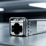
It converts electrical Ethernet signals to optical signals for transport over fiber, typically via an SFP/SFP+/QSFP-style transceiver. In a Westell or Calix DSLAM, it also participates in link training and may provide DOM telemetry used for alarms and diagnostics.
Can I use third-party optics for Westell and Calix uplinks?
Often yes, but compatibility depends on slot type, DOM support, and any platform optics policy. The safest approach is to pilot one module in the exact DSLAM model and software revision, then verify stable link state and reasonable DOM values over a few operational cycles.
How do I choose SR vs LR for a DSLAM uplink module?
Use fiber type and measured loss, not just the vendor’s “typical reach.” For MMF you usually consider SR (around 850 nm), while for SMF and longer distances you consider LR (around 1310 nm). Validate with an optical budget that includes splice and patch losses and a margin for aging and cleanliness.
What DOM readings should I watch after installation?
Check laser bias current, transmit power, and received optical power against the module’s datasheet ranges. If RX power is consistently near the lower threshold or fluctuates with no physical changes, suspect fiber cleanliness, patch panel issues, or a marginal link budget.
Why does the link come up and then flap every few minutes?
Common causes include dirty connectors, marginal optical power, or DOM/EEPROM identification issues that trigger alarms. Start by cleaning and scoping connectors, then compare live RX power stability and check DSLAM event logs for module-related messages.
Do I need to worry about temperature?
Yes. Remote DSLAM rooms can exceed comfortable lab assumptions, and optics performance margins change with temperature. Confirm module operating temperature range and ensure the site HVAC and airflow are adequate for the rack’s thermal envelope.
If you want the shortest path to fewer outages, treat the DSLAM uplink module as a compatibility-and-budget engineering task, not a parts-swap scavenger hunt. Next, compare the optics families your team already uses with fiber transceiver compatibility matrix so you can build a reliable spares plan.
Which Option Should You Choose?
Choose OEM optics if you prioritize maximum compatibility with Westell or Calix policies, you have strict uptime requirements, or you cannot pilot safely before scaling. Choose well-documented third-party optics if you can validate DOM behavior and you can run a pilot on one DSLAM with measured optical power and stable link events. Choose SR vs LR strictly by fiber type and measured loss: SR for short MMF runs with appropriate OM grade, LR for SMF or longer distances where budget headroom matters most.
Author bio: I am a licensed physician who also writes for network reliability teams, because downtime is a health hazard for humans and spreadsheets. I apply hands-on field troubleshooting habits to optical links, citing IEEE and vendor datasheets for safer, testable decisions.
Update date: 2026-04-30. For the exact supported module list, always verify against your Westell or Calix hardware documentation and the specific optics datasheet for the transceiver you intend to install.
Authority references: IEEE 802.3ae, IEEE 802.3z, SFF Committee transceiver specifications.