Modern 25G access and aggregation links often hit a port-density wall before they hit bandwidth limits. This article helps network and facilities engineers deploy double density SFP (SFP-DD) transceivers safely in real racks, with a checklist you can run during an outage window. You will get practical install steps, compatibility criteria, and field troubleshooting for the most common failure modes. Update date: 2026-04-30.
 transceiver ins")
Prerequisites before you touch the switch ports
Before ordering or installing any double density SFP, confirm your switch vendor supports the physical form factor and electrical behavior. In the field, the fastest failures come from assuming that “SFP” equals “SFP-DD” or that any 25G optics will negotiate cleanly. Plan for optics handling, optics cleaning, and a DOM verification window. Then validate that your transceiver type matches the fiber plant and link budget.
What to have on hand
- Approved transceiver list from your switch vendor (model numbers and revision notes).
- Correct fiber type: typically OM3/OM4 multimode for short reach, or single-mode for longer runs.
- Fiber inspection tool (for example, a handheld scope) and lint-free wipes.
- ESD protection and a labeled patch panel plan for move/replace work.
- Transceiver details including wavelength (for example, 850 nm SR or 1310/1550 nm LR/ER) and reach.
Key standards and what they imply
SFP-DD modules are designed for higher density while still following the SFP optical/transceiver management model used by many platforms. Link behavior is governed by IEEE Ethernet physical-layer requirements such as IEEE 802.3 for 25G Ethernet PHYs and by vendor-specific electrical constraints for host compatibility. Check vendor datasheets for DOM fields, supported digital interfaces, and any temperature or power caps. For standards context, see [Source: IEEE 802.3].
Authority references: [Source: IEEE 802.3] and your switch vendor SFP-DD support matrix. For transceiver optics characteristics, consult the module manufacturer datasheet (for example, Finisar/II-VI, Cisco, or FS.com product pages) and the host platform documentation.
Implementation steps: install and validate double density SFP for 25G
This section is written as an outage-friendly workflow you can execute in under an hour per batch of ports, assuming you have pre-cleaned patch cords and confirmed fiber mapping. The goal is to get link up with clean optics, then verify DOM telemetry and error counters. Treat transceiver insertion like a controlled change: document, validate, and only then move to the next set of ports.
Confirm the host port mode and lane expectations
On the switch, verify the port is configured for the intended speed and media. Many 25G ports accept multiple optics types, but some distinguish between SR and LR profiles. Use your platform CLI to set the port speed to 25G and confirm the interface is enabled.
Expected outcome: the port is administratively up, configured to 25G, and ready to accept the transceiver without auto-shutdown behavior.
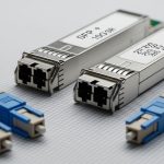
Verify transceiver compatibility using exact part numbers
Compare the module part number to the vendor’s approved list for that switch and that port group. Common field issue: a module may physically fit but fails because the host expects a specific digital ID range or power class. If you use third-party optics, confirm they advertise the right DOM schema and that the switch does not enforce “vendor-only” optics.
Expected outcome: you can show that the module model (for example, a vendor-approved SFP-DD 25G SR MMF or 25G SMF optic) is explicitly supported by the host.
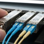
Inspect and clean fiber ends before insertion
Even with correct wavelength and reach, dirty connectors cause link flaps or high BER. Inspect both ends with a scope, then clean with approved lint-free wipes and cleaner tools. Replace any patch cords with visible scratches or contamination. If you see dust on the ferrule tip, clean until inspection shows no debris.
Expected outcome: fibers pass inspection criteria and are ready for stable optical power levels.
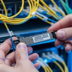
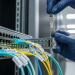
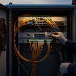
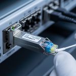
Insert the double density SFP module and seat it fully
Insert the module straight into the port until it clicks and sits flush. Avoid bending the fiber patch cord right at the cage. If your rack uses high side airflow, ensure the module housing clears any shrouds and that airflow direction stays consistent.
Expected outcome: the port identifies the module and begins optical link training.
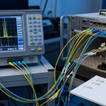
Bring the link up and verify link quality
After insertion, confirm the interface transitions to “up” and check optics and PHY counters. Validate that negotiated speed is 25G and that there are no excessive CRC or FCS errors. Most platforms expose DOM telemetry such as transmit bias current, receive optical power, and temperature.
Expected outcome: interface reports link up at 25G with stable error counters over several minutes.
Record DOM values and set an operational baseline
Capture DOM readings at install time so you can spot drift later. Typical fields include wavelength (if reported), Rx power (mW or dBm), Tx bias current, and module temperature. Store this in your change record and compare after 24 hours under normal load.
Expected outcome: a baseline exists for Rx power and temperature so you can distinguish “aging” from “fiber damage.”

Specs that matter: wavelength, reach, and optics budget
When engineers compare double density SFP options, they often look only at reach. In practice, reach depends on fiber type, connector loss, patch cord quality, and host optical power limits. For 25G, ensure the module’s supported wavelength and reach match the installed fiber plant, and that the system budget supports your channel loss.
Reference comparison table (typical 25G SFP-DD profiles)
These values vary by vendor and exact part number, so treat them as a selection starting point and confirm against the specific datasheet.
| Profile | Wavelength | Typical reach | Connector | Data rate | DOM support | Operating temperature |
|---|---|---|---|---|---|---|
| 25G SR (MMF) | 850 nm | Up to 300 m on OM3 / up to 400 m on OM4 (varies) | Duplex LC | 25.78 Gb/s | Temperature, Tx bias, Tx/Rx power (varies) | 0 to 70 C (common) |
| 25G LR (SMF) | 1310 nm | Up to 10 km (varies) | Duplex LC | 25.78 Gb/s | DOM telemetry (varies) | -5 to 70 C (common) |
Real deployment note for dense racks
In a 3-tier data center leaf-spine topology with 48-port 25G ToR switches, teams often run high port utilization during migrations. If you replace standard optics with double density SFP, you can sometimes increase usable ports per row while keeping the same 25G electrical speed class. In one rollout, a site consolidated patching by standardizing to 850 nm OM4 SR for leaf-to-spine runs under 150 m, reducing spares SKUs from four to two. The operational win came from fewer transceiver types and faster troubleshooting using consistent DOM baselines.
Pro Tip: In the field, most “bad optic” incidents are actually fiber issues. Before you swap modules, inspect and clean both ends and compare Rx power in dBm to the vendor’s allowed receiver range; if Rx power is low or drifting, the module is usually fine.
Selection checklist: choosing the right double density SFP
Use this ordered checklist during procurement and pre-stage validation. It reduces return rates and avoids downtime caused by incompatible optics or unsupported DOM behaviors.
- Distance and fiber type: match OM3/OM4 or single-mode to the module profile and verify expected link budget.
- Switch compatibility: use the approved optics list for your exact switch model and firmware release.
- Wavelength and connector: confirm 850 nm vs 1310/1550 nm and LC vs other connector styles.
- DOM support and monitoring: confirm that the host reads temperature and optical power fields you need for monitoring.
- Operating temperature: verify your rack ambient and airflow match the module spec (especially near exhaust zones).
- Power and safety limits: ensure the module’s power class stays within the host’s transceiver power budget.
- Vendor lock-in risk: if the host enforces vendor-only optics, plan spares from the same supply chain or test third-party early.
Common mistakes and troubleshooting for double density SFP
Below are the top failure modes engineers see during 25G transitions. Each includes root cause and a practical fix you can apply immediately.
Troubleshooting failure point 1: Link never comes up
Root cause: wrong module profile (for example, LR module on an SR-expected fiber plant) or incompatible DOM/ID that the host rejects. Sometimes the port is configured for a different speed or admin state.
Solution: confirm port config is 25G, validate module part number against the switch support matrix, and check interface logs for “unsupported optics” messages. If supported, reseat the module and verify fiber mapping (Tx/Rx polarity on LC jumpers).
Troubleshooting failure point 2: Link flaps or high error counters
Root cause: dirty or damaged fiber end faces, intermittent patch cord faults, or exceeding optical power receiver sensitivity after connector losses.
Solution: scope both connector ends, clean, and if needed replace jumpers. Compare Rx power from DOM to the module datasheet receiver range; if out of range, fix the channel loss (shorten run, reduce splices, replace patch cords).
Troubleshooting failure point 3: Works at low utilization, fails under load
Root cause: marginal optical budget causing BER degradation under stress, or host PHY settings that do not match (for example, auto-negotiation quirks, rare but seen during firmware transitions).
Solution: run sustained traffic (for example, iperf-style throughput tests within your lab policy) and monitor CRC/FCS and link retrains. If errors rise, re-check DOM temperature stability and Rx power; then validate firmware compatibility and PHY settings per the vendor release notes.

Cost and ROI: what to expect in real deployments
double density SFP pricing depends on wavelength (SR vs LR), fiber type, and brand. Typical market ranges for 25G SR modules are often roughly $80 to $250 per unit for third-party and $250 to $600+ for OEM-branded modules, with higher costs for long-reach variants. TCO includes not only purchase price but also failure rates, spares inventory, and labor time for troubleshooting and replacements.
ROI usually comes from two places: reduced need for additional switch hardware when density is the constraint, and faster operations when you standardize on fewer optic profiles. However, third-party optics can increase risk if your platform enforces strict optics policies or if DOM fields do not align with your monitoring thresholds. Mitigate that by running a short pilot with your exact switch model and firmware before scaling.
For vendor and third-party product examples, check manufacturer datasheets such as [Source: Cisco SFP-10G-SR family docs for form factor guidance] and module datasheets from major optics vendors like Finisar/II-VI or FS.com product listings (always verify the specific SFP-DD and 25G profile).
FAQ
What is a double density SFP (SFP-DD) compared to standard SFP?
Double density SFP (SFP-DD) is a higher-density form factor that is physically compatible with supported host cages but may not be accepted by all switches designed for standard SFP. Always rely on the vendor’s SFP-DD compatibility list rather than assuming interchangeable behavior.
Do I need a specific wavelength for 25G SR vs 25G LR?
Yes. 25G SR typically uses 850 nm for multimode fiber, while LR uses 1310 nm for single-mode. Using the wrong profile can prevent link establishment or severely limit optical margin.
Will third-party double density SFP modules work reliably?
They can, but reliability depends on strict host compatibility, DOM behavior, and optical budget match. Run a pilot in your exact switch/firmware environment and record DOM baselines before purchasing at scale.
How can I confirm optical budget without guesswork?
Use the module datasheet receiver sensitivity and your fiber channel loss estimate (cable specs plus connector/splice loss). Then validate with DOM Rx power after installation and after 24 hours of normal operation.
Why do links flap even though the interface shows “up” initially?
Flapping often points to marginal optical power, dirty connectors, or intermittent patch cord issues. Clean and re-scope fiber ends first, then compare Rx power trends and error counters over time.
What monitoring should I enable for early failure detection?
At minimum, track module temperature, Tx bias current, and Rx optical power. Set alarms when values drift beyond acceptable ranges from your install baseline, and correlate with CRC/FCS and link retrain events.
If you want a repeatable workflow for future optics refreshes, use fiber-optic-transceiver-maintenance-and-cleaning-checklist as your standard operating reference. Next, build a small “compatibility and DOM baseline” spreadsheet per switch model so every swap is faster and less risky.
Author