In day two operations, one of the most expensive “mysteries” is an SFP link that works for hours and then suddenly drops, flaps, or reports high error rates. In many cases the root cause is not optics aging or vendor incompatibility, but a dirty SFP connector on the fiber endface or the transceiver ferrule. This article helps data center and field engineers diagnose connector cleanliness issues quickly, choose the right cleaning approach, and estimate ROI from reduced truck rolls and downtime.
How a dirty SFP connector sabotages optical links

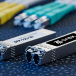
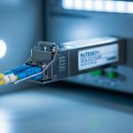
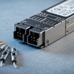
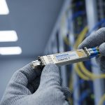
An SFP transceiver typically uses an LC duplex interface with a physical ferrule that mates to the fiber connector endface. If dust, skin oils, or residue remain on the endface, the optical path suffers from increased insertion loss and back reflections. Those effects show up as higher receive power penalties, CRC and FEC failures (when present), and eventually link down events when the receiver falls below its sensitivity margin.
What “dirty” changes in the fiber budget
Even a small speck can create a scattering site or micro-gap that increases loss. It can also raise return loss mismatch, which may couple into the transceiver receiver noise floor depending on the optical design. In practice, the link budget includes transmitter power, connector and splice loss, fiber attenuation, and receiver sensitivity; connector contamination effectively adds an unplanned loss term.
Typical symptoms you can measure
Operators often see: (1) link flaps at boot or during movement, (2) RX power trending downward while TX stays stable, (3) “Link up” but sustained packet loss, and (4) alarms like “loss of signal” or vendor-specific optical warnings. If you have optical monitoring, check that the RX power is consistent with the vendor datasheet operating range for the specific module (for example, 10G SR optics like Cisco SFP-10G-SR or Finisar/FS.com SR models).
Pro Tip: Don’t rely on “it worked yesterday” logic. Connector contamination can be intermittent: a slight change in mating pressure, cable handling, or temperature can shift the contact area and alter scattering, producing failures that look like software issues.
Field diagnosis workflow: confirm cleanliness before swapping optics
A disciplined workflow avoids unnecessary transceiver swaps and reduces mean time to recovery. Start with logs and optical telemetry, then inspect connectors, then clean and retest in a repeatable sequence. This approach matches how vendors and standards bodies recommend validating physical layer causes before assuming a transceiver defect.
capture optics and link health data
Record the current link state, interface counters, and any optical diagnostics (DOM) values exposed by your switch. On many platforms, you can pull RX power, TX bias, and temperature via vendor CLI or SNMP. If RX power is near the lower edge of the module’s expected range, connector contamination is a prime suspect.
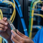
inspect with a microscope or fiber scope
Use an inspection scope designed for fiber connectors (LC, SC, MPO) with sufficient magnification to see scratches, haze, and particulate. Look for: (a) visible dust on the endface, (b) oily film (often appears as a rainbow sheen), (c) scratches that can trap debris, and (d) connector geometry mismatch that leaves an incomplete contact patch.
clean with the right method, then verify
Cleaning is not one-size-fits-all. Use lint-free cleaning wipes or alcohol-based cleaning supplies intended for fiber optics, and follow with dry removal of residue. For high-throughput environments, consider pre-saturated cleaning swabs plus a controlled technique; then re-inspect to confirm the endface is clean before reconnecting.
Key transceiver and connector specs that determine how sensitive links are
Not all SFP links fail the same way. Short-reach multimode (SR) systems can be more tolerant to small loss increases than long-reach single-mode (LR) links, but receiver sensitivity still matters. The connector type and mating interface also influence contamination risk and how quickly a dirty SFP connector can push the link outside margin.
| Spec | 10G SR SFP (Multimode) | 10G LR SFP (Single-mode) | Notes for dirty SFP connector risk |
|---|---|---|---|
| Typical wavelength | 850 nm | 1310 nm | Different wavelengths change how scattering artifacts appear to receivers. |
| Typical reach | 300 m (OM3/OM4 class) | 10 km (single-mode) | Longer reach means tighter effective margin; extra connector loss hurts more. |
| Connector interface | LC duplex (typical) | LC duplex (typical) | LC endfaces are small; contamination is easy to miss without inspection. |
| Power class (example) | Class varies by vendor; check datasheet | Class varies by vendor; check datasheet | Check DOM RX power thresholds where available. |
| Operating temperature | Often 0 to 70 C (commercial) | Often -5 to 70 C or wider (varies) | Temperature shifts can alter mating pressure and dust behavior. |
| Standards reference | IEEE 802.3 for Ethernet PHY requirements | IEEE 802.3 for Ethernet PHY requirements | Physical-layer performance must meet optical/electrical specs under expected conditions. |
When you evaluate modules, use vendor datasheets for exact optical power and receiver sensitivity ranges. For example, Cisco SFP-10G-SR optics and Finisar FTLX8571D3BCL-class devices have specific DOM behavior and power budgets documented in their datasheets. Always validate compatibility with your switch platform and firmware, because some platforms enforce optics qualification rules.
For authoritative baseline behavior of Ethernet PHY requirements, consult IEEE 802.3 material via vendor summaries, and for optical connector cleanliness practices use ANSI/TIA guidance where applicable. Source: IEEE 802.3 Source: ANSI/TIA
Selection criteria: choosing optics and cleaning practices that reduce repeat failures
Engineers often treat cleanliness as a maintenance afterthought. In reality, cleanliness is a reliability engineering variable that affects availability, spare inventory needs, and truck roll frequency. Use the checklist below when planning deployments and when diagnosing repeat faults.
- Distance and link budget margin: compute expected loss and include connector and splice loss; dirty connectors consume margin quickly on long reach.
- Switch compatibility: confirm the transceiver is supported by the exact switch model and software version; some platforms reject marginal optics.
- DOM support and thresholds: prefer modules exposing RX power and alarm flags so you can correlate failures to optical margin.
- Connector type and patch panel hygiene: LC, SC, and MPO behave differently; standardize connector kits and inspection cadence.
- Operating temperature and airflow: in hot aisles or dusty environments, contamination risk rises; design cleaning frequency accordingly.
- Vendor lock-in risk: weigh OEM modules versus third-party options; the cheapest module can be the most expensive if it triggers compatibility issues or higher failure rates.
- Cleaning workflow maturity: ensure you have inspection microscopes, approved cleaning supplies, and a documented “clean then verify” process.
Decision checklist for the next time a link flaps
Start with inspection and cleaning, not replacement. If the connector endface is clean and the link still fails, then check DOM RX power against thresholds, then validate fiber continuity and polarity (especially for MPO and duplex cabling), and finally consider swapping the transceiver if the receiver diagnostics indicate a hardware fault.
Common pitfalls and troubleshooting tips for dirty SFP connector incidents
Below are frequent failure modes field teams encounter, with root causes and practical fixes. These are the patterns that repeatedly show up in incident reviews and postmortems.
Pitfall 1: Cleaning without re-inspection
Root cause: Teams clean with wipes but skip endface verification, leaving microfilm or embedded debris. Solution: always inspect before reconnecting; use a fiber scope to confirm the endface is free of haze and particles.
Pitfall 2: Using the wrong cleaning media
Root cause: Household wipes, generic alcohol, or compressed air can spread residue or damage coatings. Solution: use fiber-optic-specific cleaning swabs, lint-free wipes, and manufacturer-approved cleaning fluids; follow a consistent technique.
Pitfall 3: Re-mating a partially contaminated connector
Root cause: If the mating interface contains debris, reconnecting can grind particles into the ferrule surface and increase permanent loss. Solution: clean both sides (transceiver and patch panel) and, if scratches or severe contamination appear, replace the affected connector or adapter.
Pitfall 4: Ignoring polarity and duplex mapping
Root cause: In duplex links, transposed transmit and receive fibers can mimic “optics failure.” Solution: verify polarity labels and test with a known-good patch; confirm the link partner uses the expected Tx/Rx mapping.
Pitfall 5: Swapping optics first during intermittent failures
Root cause: Random link flaps due to connector contamination are misdiagnosed as a bad SFP. Solution: inspect and clean first; then compare DOM readings before and after cleaning to prove causality.
Cost and ROI: cleaning discipline vs repeated downtime
Price varies by region and volume, but a realistic cost model helps justify investment. OEM SFP optics often cost more than third-party equivalents; for example, widely deployed 10G SR and LR modules can range from roughly $50 to $250 each depending on brand and reach, while inspection microscopes and cleaning kits can cost from a few hundred to several thousand dollars depending on model and magnification.
ROI usually comes from reduced truck rolls and faster recovery. If a single incident causes 30 to 90 minutes of outage risk or degraded performance, the operational cost dwarfs the module price. A cleaning program that includes scopes, standardized swab kits, and a “clean then verify” step reduces repeat failures and lowers the chance that you burn spares unnecessarily. Also account for TCO: third-party optics can be cost-effective, but compatibility issues, higher variance in DOM behavior, or inconsistent optical power can increase failure rates and labor time.
For context on connector contamination and cleaning practices, reference industry guidance such as vendor cleanliness bulletins and connector standardization documentation. Source: CommScope optical connectivity resources Source: Panduit structured cabling and fiber hygiene resources
Pro Tip: Track “cleaning events per port” over time. When a specific patch panel or adapter set repeatedly fails, the ROI shifts from buying more transceivers to replacing that hardware batch and tightening installation handling.
FAQ
What does a dirty SFP connector look like under a fiber scope?
You may see visible dust particles, a hazy film, or oil sheen on the endface. Scratches can also appear and trap debris, making the connector look “clean enough” to the eye while still causing measurable loss.
Can I fix a dirty SFP connector without removing the transceiver?
Sometimes you can clean the patch panel side first, but the transceiver ferrule endface also needs inspection when failures repeat. If the transceiver is suspected, remove it and clean both mating surfaces to prevent grinding contamination into the ferrule.
Will cleaning restore link stability immediately?
In many cases, yes. If you observe RX power rise toward expected values and error counters drop after cleaning and re-inspection, you have strong evidence the root cause was connector cleanliness.
Do third-party SFP modules worsen dirty connector issues?
They do not inherently cause contamination, but they can have tighter operating margins or different DOM alarm behaviors. If your platform has strict optics qualification, a marginal optical budget combined with contamination can trigger failures sooner.
How often should we clean and inspect connectors in a data center?
There is no single universal schedule; it depends on environment dust levels, move-add-change frequency, and whether connectors are frequently unplugged. A practical approach is periodic inspection plus cleaning on every reconnection event for critical paths.
What is the fastest troubleshooting order for link down problems?
Verify counters and DOM readings first, inspect connector endfaces next, clean and re-inspect, then validate fiber polarity and continuity. Only after physical layer checks show no issue should you replace optics.
If you want to prevent dirty connector incidents from recurring, standardize the inspection and cleaning workflow and verify outcomes with DOM and scope evidence. Next, review fiber optic connector cleaning best practices to build a repeatable maintenance process that improves availability.
Author bio: I deploy and troubleshoot fiber and Ethernet transceivers in live data center environments, using DOM telemetry and fiber scopes to isolate physical-layer root causes. I also advise on reliability ROI models that balance OEM versus third-party optics, cleaning tools, and operational downtime risk.