A directionless DWDM ROADM can look simple on a rack diagram, but the transceiver details decide whether wavelengths light up on the first install or spend weeks in troubleshooting. This guide helps network engineers and field technicians specify and validate colorless, directionless ROADM optics—focused on what to buy, what to measure, and where failures usually hide. You will leave with a practical checklist, a spec comparison table, and concrete pitfalls to prevent.
How directionless DWDM changes transceiver requirements in ROADM
In a conventional fixed-wavelength design, optics can be tuned tightly to a known grid position. With directionless DWDM, the ROADM fabric routes wavelengths without needing a separate “per direction, per color” plan at each site, so transceivers must support flexible wavelength behavior and consistent optical performance. In colorless operation, you typically use similar “color-agnostic” coherent pluggables at the client side, then rely on the ROADM to select and route the right wavelength. That shifts your risk toward optical interface compatibility, coherent tuning behavior, and DOM telemetry alignment with the ROADM controller.
Practically, you are matching three layers: (1) the client transceiver electrical interface (often OTN or Ethernet framing), (2) the coherent optical characteristics (wavelength stability, OSNR, launch power), and (3) the ROADM transponder/receiver expectations (grid compliance, monitoring, and alarms). If any layer is off by a small margin, the ROADM may still “see light,” but it can fail to lock, fail OSNR thresholds, or mis-handle channel power balancing.
What “directionless DWDM” implies for optical control
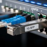
Field teams usually verify that the transceiver supports the same ITU-T grid spacing and that its tuning range matches the ROADM’s allowed channel plan. Many deployments use 50 GHz or 25 GHz grids; the transceiver must land on the exact channel center within vendor-stated accuracy. Also confirm whether your coherent optics require a specific laser line width / coherence setting to work with the ROADM’s filtering and impairments budget.
Pro Tip: In colorless directionless ROADM installs, the “first-pass success” often depends more on DOM telemetry mapping than on raw optical reach. If the ROADM expects specific DOM fields (for example, vendor-specific alarm thresholds or calibration identifiers), mismatched modules can trigger false “channel out of spec” alarms even when the waveform is otherwise valid.
Key transceiver specs to match for directionless DWDM ROADM
Use the table below as a field-oriented starting point. Exact values vary by vendor and modulation format, but these are the parameters that most commonly break compatibility during ROADM bring-up. Always cross-check with the specific ROADM vendor’s transceiver compatibility matrix and the transceiver datasheet.
| Spec to verify | Why it matters in directionless DWDM | Typical target range (example) | Where to confirm |
|---|---|---|---|
| Wavelength grid and tuning | Must land on ROADM channel plan precisely | 50 GHz grid; tuning accuracy often within a few GHz | Transceiver tuning specs + ROADM channel plan |
| Channel spacing support | ROADM filtering and mux/demux alignment | 25 GHz or 50 GHz support | ROADM and transceiver interoperability docs |
| Launch power range | ROADM power leveling and OSNR budget | Coherent modules often specify a per-channel launch window | Transceiver optical output power specs |
| Receiver sensitivity / OSNR requirement | Determines whether ROADM can lock and demodulate | Depends on modulation and FEC | Datasheet OSNR and sensitivity curves |
| Modulation and line rate | ROADM impairment assumptions and DSP mode | Common: coherent 100G/200G/400G variants | ROADM transponder mode support |
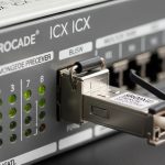
| Connector and optical interface | Prevents physical mismatch and reflection issues | LC/UPC or SC depending on system design | Patch panel and transceiver interface type |
| Temperature range | Stability of wavelength and output power | Commercial often 0 to 70 C; some deployments require wider | Transceiver operating range |
| DOM support and alarm behavior | ROADM alarms and automated provisioning | Vendor-specific DOM fields and thresholds | DOM documentation + ROADM expectations |
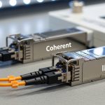
For concrete examples, many coherent optics in the field are compatible with common transceiver form factors and vendor ecosystems. You might see modules like Cisco SFP-10G-SR in legacy short-reach contexts, but coherent directionless DWDM typically uses specialized coherent pluggables or transponders rather than 10G SR optics. For tunable coherent families, vendors often publish wavelength tuning and OSNR requirements in their datasheets; for example, Finisar and similar vendors publish detailed tuning and performance parameters for coherent optics in their product literature.
When you select, focus on the intersection of: the ROADM’s supported modulation formats and channel grid, and the transceiver’s tuning, launch power, and OSNR. If the ROADM requires a specific coherent DSP mode or FEC configuration, treat it as a hard requirement, not a “best effort.”

Deployment scenario: colorless directionless ROADM in a leaf-spine network
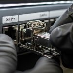
Imagine a 3-tier data center network with 48-port 10G and 25G ToR switches feeding 100G aggregation, plus two regional sites connected by a metro DWDM ring. At the metro sites, you deploy a colorless directionless ROADM to route up to 32 channels across a 50 GHz grid, with each channel carrying 200G coherent traffic. The transceivers sit in the ROADM line interface cards and are provisioned via an orchestration system that reads DOM telemetry and applies per-channel power leveling. During installation, the field team sets the expected launch power window (for example, within a vendor-stated dBm range) and confirms wavelength landing using the ROADM’s channel monitoring.
Operationally, engineers schedule a “bring-up window” where they: (1) verify module DOM compatibility, (2) confirm channel activation at the ROADM controller, (3) measure OSNR and confirm it exceeds the transceiver/FEC threshold, and (4) run a continuity test with expected bit error performance. In one common failure mode, the wavelength appears correct, but OSNR is slightly low due to an unexpected patch panel loss budget; the ROADM then refuses to keep the channel in service. This is why link budgets and power leveling assumptions must match the real fiber plant.
Selection checklist for directionless DWDM transceivers
Use this ordered checklist like a pre-flight. It is short on theory and heavy on decision points.
- Distance and reach: Confirm span loss and margin, including connector and splice losses. Ensure the transceiver OSNR requirement is met at the far end.
- Grid and tuning compatibility: Match ROADM channel plan (25 GHz or 50 GHz), supported tuning range, and channel center accuracy.
- Switch and ROADM compatibility: Verify the ROADM vendor’s transceiver compatibility matrix for your exact module part number and form factor.
- DOM support: Confirm DOM fields, alarm thresholds, and whether the ROADM controller expects vendor-specific calibration data.
- Operating temperature: Validate the module’s temperature range against enclosure airflow and worst-case ambient conditions.
- Operating power and launch window: Ensure the module can be set or auto-leveled within the ROADM’s power leveling policy.
- Vendor lock-in risk: Balance OEM modules versus third-party compatible optics. Plan for spares and validate interoperability in a lab before scaling.

Common mistakes and troubleshooting tips
Below are frequent field issues with root causes and fixes. They are ordered by how often they appear during first installs.
Wavelength mismatch despite “channel up”
Root cause: The transceiver tunes to the wrong channel center or drifts due to temperature/aging, often because the ROADM expects a different grid plan or calibration baseline. Sometimes the channel appears active but fails framing or stays in a degraded state.
Solution: Confirm the ROADM channel plan (25 GHz vs 50 GHz) and verify the module’s channel center accuracy. Re-run wavelength calibration if the platform supports it, and check enclosure airflow and ambient temperature.
OSNR too low after installing new patch panels
Root cause: Extra insertion loss from patch panels, dirty connectors, or unexpected bend radius increases attenuation and degrades OSNR. In directionless DWDM, the ROADM cannot “route around” a too-low OSNR budget.
Solution: Clean and inspect connectors with proper inspection tools, verify fiber loss with OTDR or certified loss testing, and compare measured results against the planned link budget. Adjust launch power only within the allowed window; do not exceed vendor limits.
DOM alarms block provisioning or cause “out of service”
Root cause: Third-party modules may provide DOM data, but not in the exact format or threshold behavior expected by the ROADM controller. This can trigger protective shutdowns even when optics are physically aligned.
Solution: Validate DOM compatibility during acceptance testing. If your ROADM supports it, update the controller software to match the transceiver DOM behavior, or restrict to modules listed in the compatibility matrix.
Connector or polarity errors on fiber paths
Root cause: LC polarity reversal or wrong patch cord type can create reflection and reduce receiver performance. This is more common when crews reuse patch panels between projects.
Solution: Verify patch cord type, polarity, and labeling. Use loopback tests where possible and correlate optical power levels with expected values from the datasheet.
Cost and ROI note for directionless DWDM transceiver choices
In practice, coherent transceivers for directionless DWDM ROADM scenarios often cost significantly more than simpler fixed-wavelength optics. Typical market pricing can range from roughly several thousand to tens of thousands of dollars per module, depending on line rate and modulation. OEM optics usually carry lower integration risk but higher unit cost; third-party modules can reduce purchase price, yet may increase engineering time for DOM and compatibility validation.
ROI comes from fewer truck rolls and faster onboarding. If a mismatch causes even a 1 to 2 week delay for a metro service window, the labor and downtime costs can outweigh the unit price difference. For TCO, include spares strategy (how many modules you must keep on hand), expected failure rates, and how quickly you can swap a module without waiting for long lead times.
[[IMAGE:Warm lifestyle-style photo of a field engineer in a server room using a handheld optical power meter and laptop near a ROADM chassis, with visible