Carrier MPLS WAN links fail more often from optics mismatches than from routing mistakes. This guide helps field engineers and transport teams plan, validate, and commission carrier ethernet SFP transceivers for WAN optical handoffs, with practical checks for DOM, power budgets, and temperature margins. You will also get a troubleshooting playbook for common link-down and high-error cases, plus a cost and ROI view for OEM versus third-party optics.
Prerequisites for MPLS WAN links using carrier ethernet SFP
Before you touch the shelf, confirm that the physical layer and the transport layer agree on speed, encoding, and optics class. In MPLS WAN deployments, the optical layer must be stable long enough to complete OAM, management polling, and any service-level activation workflow.
Network and hardware prerequisites
-
Switch/router model and optics matrix: Verify the platform supports the target SFP family (for example, 10GBASE-SR, 10GBASE-LR, or 1000BASE-LX) and the exact vendor/part compatibility list. Many carrier edge routers enforce optic vendor checks via vendor-specific EEPROM fields.
-
Fiber type and plant records: Confirm whether you have OM3/OM4 multimode or OS2 single-mode, and verify connector type (LC/APC vs LC/UPC) from splicing logs. If your records are stale, measure end-to-end loss and reflectance rather than trusting the spreadsheet.
-
Expected link rate and encapsulation: MPLS WAN often runs over Ethernet (for example, 10G or 1G) with L2/L3 services above. Your carrier ethernet SFP must match the port speed, not just “Ethernet in general.”
-
Test equipment: Have an optical power meter and a stable optical light source or transceiver tester. For commissioning, also have a soft tool to read DOM (Digital Optical Monitoring) values from the switch.
Expected outcome: A confirmed optics-and-fiber plan that matches port speed, connector type, and optics wavelength. You will also have a way to validate DOM thresholds after insertion.

Step-by-step implementation: commission carrier ethernet SFP for MPLS WAN optics
This section is written as a numbered commissioning runbook. Follow it in order to minimize avoidable outages and reduce time lost to optics incompatibility or fiber loss miscalculation.
Select the correct SFP class for the distance and wavelength plan
Start with the physical reach requirement and the fiber class. In practice, MPLS WAN links may use 10G optics over OS2 for 20 km to 80 km spans, or 1G optics for shorter metro runs. Pick the module type based on wavelength and the expected attenuation budget, not on “it should work” assumptions.
Expected outcome: A shortlist of SFP types (for example, 10GBASE-LR at 1310 nm, 10GBASE-ER at 1550 nm, or 1000BASE-LX at 1310 nm) that align with measured fiber plant.
Validate switch compatibility and DOM behavior
Insert optics only after confirming platform compatibility. If you cannot use the vendor’s certified optics list, at least validate that the switch reads DOM fields: laser bias current, received power, transmit power, and temperature. Some platforms reject “non-compliant” EEPROM layouts even if the transceiver electrically meets the standard.
For example, many deployments use transceivers like Cisco SFP-10G-SR in compatible environments, or third-party equivalents such as Finisar FTLX8571D3BCL and FS.com SFP-10GSR-85 where the switch supports that EEPROM profile. Always verify with your exact hardware revision.
Expected outcome: The switch shows the link as “up” at layer 1 and reports DOM values without alarms.
Compute and verify optical power budget with margin
Use power budget math that includes connector loss, splice loss, and aging margin. A field rule that saves time: budget at least 3 dB of implementation margin beyond your calculated plant loss, because patch cords and cleaning quality often introduce extra attenuation.
Example approach (engineer-friendly):
- Start with transceiver Tx/Rx power specifications (worst-case).
- Add fiber attenuation (dB/km) times span length.
- Add connector and splice losses (for instance, 0.2 dB per mated LC connection and 0.1 dB per splice as a starting point; replace with your measured values).
- Confirm receiver sensitivity and that measured Rx power lands in the switch’s acceptable DOM window.
Expected outcome: A budget that predicts stable operation at temperature extremes and after typical aging.
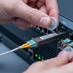
Inspect fiber endfaces and clean before insertion
Most “mystery” MPLS WAN link failures trace back to contaminated connectors. Clean both ends of the LC connectors and verify with an inspection microscope. Use APC where required; mixing UPC and APC can create back-reflection issues that show up as intermittent errors.
Expected outcome: Reduced insertion loss and stable received power readings immediately after commissioning.
Insert optics with correct polarity and verify link metrics
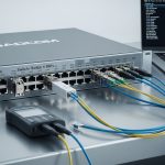
Confirm transmit-receive polarity. For Ethernet optics, Tx must go to the far Rx. On patch panels, label the fibers and validate with a continuity test before final insertion. After link up, record DOM values and interface counters (CRC errors, errored frames, and any optical alarms).
Expected outcome: Layer 1 up, minimal optical alarms, and clean layer 2 behavior suitable for MPLS activation.

Key carrier ethernet SFP specs that matter in WAN optical links
Engineers often compare only wavelength and “reach,” but MPLS WAN reliability hinges on power levels, DOM thresholds, connector type, and temperature performance. Below is a practical comparison of common SFP classes used for carrier Ethernet over WAN.
| Parameter | 10GBASE-SR (850 nm) | 10GBASE-LR (1310 nm) | 10GBASE-ER (1550 nm) | 1000BASE-LX (1310 nm) |
|---|---|---|---|---|
| Typical data rate | 10.3125 Gb/s | 10.3125 Gb/s | 10.3125 Gb/s | 1.25 Gb/s |
| Wavelength | 850 nm | 1310 nm | 1550 nm | 1310 nm |
| Typical fiber | OM3/OM4 multimode | OS2 single-mode | OS2 single-mode | OS2 single-mode |
| Common reach class | Up to ~300 m on OM3/OM4 (varies by vendor) | Up to ~10 km (varies) | Up to ~40 km or more (varies) | Up to ~10 km (varies) |
| Optical interface | LC | LC | LC | LC |
| DOM support | Common (temperature, bias, power) | Common (temperature, bias, power) | Common (temperature, bias, power) | Common (temperature, bias, power) |
| Operating temperature | Often 0 to 70 C (commercial) or wider options | Often 0 to 70 C (commercial) or wider options | Often -5 to 85 C (varies by part) | Often 0 to 70 C (commercial) or wider options |
Standards alignment matters: Ethernet optical transceivers are defined by the relevant IEEE specifications for the physical layer (for example, IEEE 802.3 for 10GBASE-SR/LR/ER and 1000BASE-LX). For the SFP mechanical and electrical interface, the SFP Multi-Source Agreement (MSA) defines the module footprint and electrical behavior.
Sources: IEEE 802.3 Optical PHY clauses and SFP MSA and transceiver documentation summaries.
Pro Tip: When you commission an MPLS WAN circuit, do not just verify “link up.” Capture DOM Tx power, Rx power, and module temperature at installation time, then compare those values to your switch’s alarm thresholds. If Rx power sits near the lower bound, you may pass initial tests but fail during seasonal temperature drift or after a cleaning event elsewhere in the patch panel.
Selection criteria checklist for carrier ethernet SFP in MPLS WAN
Use this ordered checklist so the decision is repeatable across sites and contractors. In carrier environments, consistency beats heroics during outages.
-
Distance and fiber type: Choose multimode versus single-mode, then map to wavelength (850 nm vs 1310 nm vs 1550 nm). Confirm span length and number of connectors/splices.
-
Optical budget with margin: Ensure calculated worst-case receive power is comfortably above the sensitivity floor. Target at least 3 dB operational margin for real plant variability.
-
Switch and port compatibility: Validate the exact SFP family supported by the router/switch. Some platforms enforce vendor checks even when the PHY is standard.
-
DOM and alarm integration: Confirm the platform can read DOM fields and that the module provides correct EEPROM values. This is critical for automated monitoring and trouble ticket correlation.
-
Operating temperature and thermal design: For outdoor cabinets or hot aisles, pick modules rated for the environment. Temperature affects laser bias and optical output stability.
-
Vendor lock-in risk: OEM optics can reduce compatibility uncertainty but increase unit cost. Third-party optics can lower CAPEX but can create support friction during RMA and incident investigations.
-
Connector and polarity plan: Ensure LC connector type and patch panel labeling match the Tx/Rx polarity. Plan cleaning and inspection at install and after maintenance.
Expected outcome: A defensible selection that minimizes “it worked in the lab” surprises and supports predictable operations.
Common mistakes and troubleshooting for MPLS WAN optics
Below are the top failure modes seen in field operations. Each includes a root cause and a practical remedy that you can apply during the next truck roll.
Failure point 1: Link does not come up after SFP insertion
Root cause: SFP incompatibility with the platform (EEPROM vendor/profile mismatch) or wrong speed expectation on the port. In some carrier routers, the optics is electrically present but the port refuses to initialize due to DOM or vendor fields.
Solution: Confirm the port configuration matches the optics type (for example, 10G vs 1G). Swap to a known-compatible optic (from the platform’s certified list) and verify DOM reads. If DOM does not populate, suspect EEPROM profile mismatch.
Failure point 2: Link flaps or MPLS LSP setup fails intermittently
Root cause: Contaminated connectors or incorrect polarity causing marginal received power with bursts of errored frames. In metro patch panels, dust can be worse than you expect after prior maintenance.
Solution: Clean both ends with proper fiber cleaning tools, inspect with a microscope, and re-seat connectors. Validate Rx power via DOM and compare to the receiver threshold range. Also confirm Tx/Rx polarity on the patch cords and panel.
Failure point 3: High CRC or errored frames despite “link up”
Root cause: Optical power budget too tight, fiber bend/strain damage, or aging. High-error cases often show Rx power near the lower margin and increased module temperature.
Solution: Measure optical power at commissioning time and after any suspected disturbance. Check for fiber routing stress (especially near cable trays) and verify splices/connectors. If the budget is tight, replace the optic with a higher-reach class (for example, LR to ER) or improve the plant with lower-loss jumpers.
Cost, TCO, and ROI considerations for carrier ethernet SFP optics
In real deployments, optics cost is only part of total cost of ownership. Truck rolls, downtime penalties, and support delays often dominate the TCO when optics compatibility is uncertain.
Typical price bands vary by vendor, temperature grade, and reach:
- OEM-certified SFP (commercial temp): often higher unit cost, commonly in the tens to low hundreds of currency units per module depending on rate and reach.
- Third-party SFP: frequently cheaper, but verify EEPROM/DOM compatibility and ensure the supplier provides spec sheets and DOM behavior documentation.
ROI guidance: if your sites are high-risk (outdoor cabinets, hot aisles, limited maintenance windows), pay for compatibility certainty (OEM or tightly validated third-party). For low-risk controlled data centers, third-party optics can be economical if you maintain a strict compatibility test and burn-in process.
Expected outcome: A procurement plan that balances CAPEX with operational reliability and supportability.

FAQ
What does a carrier ethernet SFP typically support for MPLS WAN?
In most MPLS WAN designs, the SFP provides the Ethernet PHY on the WAN-facing port (for example, 10GBASE-LR/ER or 1000BASE-LX). MPLS runs above Ethernet, so the optics must match the port speed and physical reach. Always validate the exact optics type your platform expects.
Can I use third-party optics instead of OEM modules?
Yes, but compatibility is not guaranteed. You must confirm EEPROM/DOM behavior and that the platform accepts the module vendor profile. In carrier environments, keep a test matrix and track which optics have passed burn-in and incident-free operation.
How do I confirm DOM values are healthy after insertion?
Check the switch interface diagnostics for module temperature, transmit power, receive power, and any optical alarms. Compare those values to your platform’s thresholds and your module datasheet. If DOM is missing or shows out-of-range values, treat it as a commissioning failure.
What fiber cleaning interval should we use for WAN optics?
At minimum, clean before first insertion and after any maintenance that touches patch cords or panel hardware. For high-error incidents, clean and inspect immediately before swapping optics. In practice, connector contamination is a top cause of intermittent CRC and link flaps.
Which reach class should I choose: LR or ER?
Choose based on measured plant loss and margin. If your link budget is tight or spans include extra connectors/splices, ER can provide more margin on OS2. However, ER optics are typically more expensive, so only upgrade when the budget calculation justifies it.
How should we document optics and fiber changes to reduce repeat outages?
Record the exact transceiver part number, serial number, DOM snapshot, and the fiber path identifiers for each endpoint. Also log connector types and any cleaning/inspection results. This reduces mean time to repair when a similar problem occurs at another site.
Carrier MPLS WAN success with carrier ethernet SFP depends on disciplined optics selection, verified optical budgets with margin, and repeatable commissioning checks. If you want the next step, review carrier ethernet handoff and OAM validation to align optical readiness with service activation and monitoring.
Author bio: I am a telecom engineer who has commissioned MPLS over Ethernet transport in metro and carrier-edge environments, focusing on optical power budgets, DOM alarms, and DWDM-to-PON handoff edge cases. I write from field experience with SFP/SFP+ optics, connector hygiene practices, and operational troubleshooting workflows.