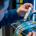
If your Google Cloud Dedicated Interconnect link is flaky, most teams first suspect routing or VLAN config. In practice, optical layer problems are often the real cause: wrong transceiver type, marginal link budget, or DOM mismatch with the switch. This article helps network engineers and field technicians choose the right Dedicated Interconnect transceiver for fiber-based Dedicated Interconnect handoffs, with concrete specs, compatibility checks, and troubleshooting steps.
What Google Cloud Dedicated Interconnect expects at the optics layer
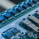
Google Cloud Dedicated Interconnect is delivered as a physical fiber handoff into your environment, typically using standard Ethernet over fiber optics. Your side must provide a transceiver that matches the switch port type (speed, form factor, and optical interface) and fits the installed fiber plant (single-mode vs multi-mode, core size, and connector geometry). For most production deployments, you should plan around single-mode fiber (SMF) and optics aligned to IEEE 802.3 Ethernet PHY requirements.
Match form factor and data rate to the switch and port
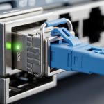
Dedicated Interconnect circuits are commonly provisioned at 10G or 100G Ethernet rates depending on your design. The transceiver must match the switch module: for example, SFP+ for 10G, QSFP+ for 40G, and QSFP28/QSFP56 for 100G-class ports. If you attempt to run a 100G transceiver on a 40G port (or vice versa), the link will never train.
Choose the correct fiber and connector type
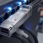
Most Dedicated Interconnect designs use SMF with either LC connectors and optics specified for the relevant wavelength. Common examples include 10G SR (typically multimode, short reach) and 10G LR (single-mode, long reach). In many enterprise and carrier-grade builds, LC/UPC and SMF are the practical baseline because they reduce connector-related return loss issues.
Pro Tip: Treat DOM telemetry as a commissioning requirement, not a nice-to-have. If your switch or optics management system flags “DOM present but invalid” (or reports out-of-range temperature/voltage/bias), you can see intermittent CRC errors even when the link comes up. Log optical power and DOM readings during initial cutover, not after the first outage.

Optics types that work in Dedicated Interconnect designs
Dedicated Interconnect links are usually engineered with a predictable optical budget. That budget is dominated by fiber attenuation, connector/splice losses, and the transceiver’s transmit power and receiver sensitivity at the target wavelength. The “right” transceiver is the one that meets the budget with margin across temperature and aging.
10G-class single-mode options (common in 10G Dedicated Interconnect)
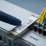
For 10G Ethernet over SMF, you will typically see 1310 nm long-reach optics (often marketed as LR) with LC connectors. A practical reference point: Finisar-compatible optics such as FTLX8571D3BCL (10G LR class) are widely used in the field where the switch supports the vendor or tolerates third-party optics. On the Cisco side, you may also encounter Cisco-branded optics like Cisco SFP-10G-LR variants that match specific platform compatibility lists.
40G/100G-class single-mode options (common in higher capacity designs)
For 100G over SMF, you’ll often encounter QSFP28 1310 nm optics using either a single wavelength approach or a multi-lane architecture (implementation depends on the vendor). For deployment planning, use the datasheet’s “minimum receiver sensitivity” and “maximum launch power” rather than marketing reach claims.
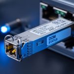
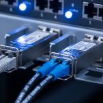
DOM, speed, and electrical interface compatibility
Most operational failures come from compatibility gaps: the transceiver is physically present but the switch refuses it, or it trains at a lower mode. Verify that the transceiver supports the exact interface required by the switch port (for example, 10G SFP+ electrical lanes vs 100G QSFP28 lane mapping). Also check DOM support: the switch should read temperature and optical power without errors.
Key specifications that decide pass/fail for your fiber link
Engineers win these projects by comparing a handful of optics parameters to the actual fiber plant. The table below summarizes the fields that matter most for Dedicated Interconnect transceiver selection and acceptance testing.
| Specification | What to verify | Typical values (examples) |
|---|---|---|
| Data rate | Matches switch port speed and lane mapping | 10G (SFP+), 100G (QSFP28) |
| Wavelength | Aligns with SMF design and vendor optics | 1310 nm common for SMF LR |
| Reach | Must exceed installed distance plus margin | Vendor-rated ranges; confirm against budget |
| Tx power range | Ensures enough launch power after losses | Use datasheet min/max, not marketing |
| Rx sensitivity | Determines receiver margin for BER targets | Minimum sensitivity at target BER |
| Connector type | LC/UPC vs LC/APC affects return loss | Often LC/UPC in data centers |
| DOM support | Switch reads temperature and optical power | Digital diagnostics per SFF-8472/SFF-8431 class |
| Operating temperature | Must cover room and enclosure conditions | Common ranges: commercial vs industrial grades |
Turn those specs into a link budget with margin
A field-ready approach: compute total link loss as fiber attenuation (dB/km) times distance plus connector loss and splice loss. Then compare against the transceiver budget: ensure received power stays above the receiver sensitivity with a margin that accounts for temperature drift and connector re-mating. For acceptance, log Rx optical power at link-up and after 24 hours under stable load.

Selection checklist for a Dedicated Interconnect transceiver
Use this ordered checklist like a commissioning script. It reduces “it came up on the bench but fails in production” scenarios.
- Distance and fiber type: confirm SMF vs MMF, and measure or verify the installed length (including patch panel routing).
- Speed and form factor: map the Dedicated Interconnect interface rate to the switch port (SFP+, QSFP28, etc.).
- Wavelength and reach: select optics whose wavelength matches the plant design (commonly 1310 nm for SMF LR) and whose rated reach exceeds the distance with margin.
- Optical budget math: use vendor datasheet Tx power and Rx sensitivity; include connector loss and splice loss; verify received power stays within the transceiver’s operating range.
- DOM support and telemetry sanity: confirm your switch can read DOM without “unsupported” or “fault” states; plan to record Tx/Rx power and temperature during cutover.
- Operating temperature: verify the transceiver grade matches your rack environment; avoid using commercial-grade optics in hot aisles.
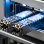
- Switch compatibility and vendor lock-in risk: check the switch vendor’s compatibility list; decide between OEM optics and third-party optics based on your change control and RMA process.
- Connector standardization: standardize on LC/UPC or LC/APC as designed; ensure consistent polish and cleaning practices.
Compatibility reality: OEM vs third-party
OEM optics (for example, Cisco-branded modules) often have the lowest friction with platform diagnostics and firmware expectations, but they can carry a higher purchase price. Third-party optics from vendors such as Finisar/Lumentum or reputable module houses (for example, FS-branded optics like FS.com SFP-10GSR-85 in appropriate cases) can reduce cost, but you must validate DOM behavior and switch acceptance. Always confirm the exact part number your switch supports, not just “same wavelength and same reach.”
Common mistakes and troubleshooting steps
When Dedicated Interconnect transceivers misbehave, symptoms can look like routing issues. Below are common failure modes with root causes and practical fixes.
Link comes up briefly, then CRC/packet loss spikes
Root cause: insufficient optical margin due to underestimated connector/splice losses or a transceiver with marginal Tx power. Sometimes the fiber is longer than the documented cut length because patch routing changed during installation. Solution: measure Rx optical power at the switch, compare to the transceiver datasheet sensitivity, and re-check the link budget. If Rx power is near the sensitivity threshold, replace the optics with a higher-power or better-reach model, or fix the fiber plant (clean/re-terminate, reduce splices).
Switch reports “unsupported transceiver” or port stays down
Root cause: transceiver is not electrically compatible with the port, or the switch enforces an allowlist for DOM vendor IDs. Solution: verify form factor and speed (SFP+ vs QSFP28 vs QSFP56) and confirm part numbers against the switch vendor’s compatibility guidance. If you must use third-party optics, test in a maintenance window and capture switch logs that show the rejection reason.
DOM telemetry shows invalid or fluctuating readings
Root cause: poor contact in the cage, marginal transceiver seating, or a cleaning issue that causes intermittent optical signal and DOM compensation behavior. Solution: remove and re-seat the module, clean connectors with lint-free wipes and proper alcohol-compatible cleaning tools, then re-measure optical power. If DOM temperature readings jump erratically, inspect for mechanical stress and verify the module is not counterfeit.
Wrong fiber polarity or swapped fibers
Root cause: in duplex LC cabling, transmit/receive fibers can be reversed at one end, leading to no link or intermittent link depending on transceiver behavior. Solution: identify polarity using a known-good “A to A” or “Tx to Rx” labeling scheme, then swap the fibers or use a polarity patch (where appropriate). After correction, verify link training and check optical power readings for stability.
Cost and ROI note for Dedicated Interconnect transceiver choices
In 10G SMF deployments, optics prices vary widely by OEM vs third-party and by grade (commercial vs industrial). A realistic purchase range for tested 10G SMF LR optics in enterprise procurement is often roughly $50 to $250 per module, while 100G-class optics can be materially higher depending on vendor and reach class. TCO should include labor for validation, risk of downtime during RMA, and the cost of repeated cleaning/patching. In many environments, the ROI comes from reducing change-control friction: OEM optics may cost more upfront but can reduce commissioning time and failure rate during initial handoff.
For standards context, the optical interface expectations align with IEEE 802.3 Ethernet PHY behavior and the small form-factor transceiver digital diagnostics conventions used by many modern modules. For deeper reference, see [Source: IEEE 802.3] and vendor datasheets for exact power and sensitivity parameters. IEEE Standards Association
FAQ
How do I know which Dedicated Interconnect transceiver type to buy?
Start with your switch port speed and form factor, then confirm fiber type (usually SMF) and connector standard (commonly LC). After that, compute a link budget using the transceiver datasheet Tx power and Rx sensitivity, and verify received power stays above sensitivity with margin.
Can I use third-party optics for Google Cloud Dedicated Interconnect?
Yes in many cases, but you must validate compatibility with your specific switch model and its optics policy. Confirm DOM telemetry works cleanly and that the switch does not reject the module based on vendor identifiers.
What optical power numbers should I watch during cutover?
Log both transmit and receive optical power from DOM immediately after link-up, then re-check after a short stability period. Compare Rx power to the module’s minimum sensitivity and ensure it remains stable; large swings often indicate cleaning, connector seating, or fiber polarity issues.
Is DOM telemetry required for the link to work?
The physical Ethernet link can sometimes train without full DOM integration, but your operational monitoring and diagnostics depend on it. Many platforms will still bring the link up while flagging warnings; those warnings can correlate with rising BER and future outages.
Why does the link fail only after a few hours?
Common causes include thermal drift in a marginal link budget, a connector that is not fully seated, or intermittent contamination that worsens with airflow and temperature changes. Measure optical power over time and inspect/clean connectors if the failure correlates with environmental conditions.
How much margin should I plan for?
A practical rule is to include enough margin to cover connector re-mating, minor fiber attenuation variance, and temperature effects. Your exact margin depends on the transceiver’s Rx sensitivity curve and the link budget inputs, but commissioning should never rely on “near-threshold” operation.
As a field-focused network professional, I recommend treating the Dedicated Interconnect transceiver as a system component: optics, fiber plant, switch compatibility, and DOM telemetry must be validated together. Next, align your cabling and polarity documentation with your transceiver selection using fiber polarity and connector cleaning best practices.
Author bio: I deploy and troubleshoot Ethernet over fiber links in production data centers and interconnect environments, with hands-on optical power and DOM commissioning experience. I write from the perspective of what actually fails under maintenance windows, inspections, and RMA cycles.