If your Google Cloud Dedicated Interconnect is timing out, flapping, or never coming up, the root cause is often not routing. It is frequently the Dedicated Interconnect transceiver selection: optics type, wavelength, reach, DOM signaling, and connector polish. This guide helps network engineers and field technicians choose the right fiber transceiver for a reliable on-ramp between your on-prem network and Google Cloud, with practical checks before you touch live hardware.
What a Dedicated Interconnect transceiver must do for Google Cloud
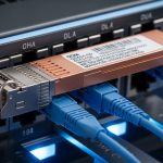
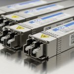
Dedicated Interconnect (D I) uses Ethernet transport over fiber, so the transceiver must match the physical layer expectations of both ends: your router or switch optics and the provider handoff. In practice, this means selecting the correct data rate (commonly 1G/10G), optical wavelength band (for example, 850 nm multimode or 1310/1550 nm single-mode depending on reach), and connector standard (LC is common). You also must ensure your switch supports the transceiver type and that DOM (Digital Optical Monitoring) is readable, since many platforms enforce DOM presence or thresholds.
Fiber type, optics band, and connector mapping
Most Google Cloud D I handoffs are designed around standard Ethernet optical interfaces. Your job is to map your service port requirements to a compatible transceiver: OM3/OM4 multimode for shorter distances at 850 nm, and OS2 single-mode for longer spans at 1310 nm or 1550 nm. Connector cleanliness matters at least as much as wavelength; a single contaminated LC ferrule can produce errors that look like link instability.

Key specifications table: what to compare before you buy
Engineers often compare only reach, but failures usually happen due to mismatched wavelength, wrong optics class, or unsupported transceiver form factors. Use the following table as a field checklist for typical 10G and 1G optics used in interconnect designs. Always validate with your vendor datasheet and your switch’s transceiver compatibility matrix.
| Spec category | Typical option | What it affects | Example transceiver models |
|---|---|---|---|
| Data rate | 1G (1.25Gbaud) or 10G (10.3125Gbaud) | Line coding and link training | Cisco SFP-10G-SR, FS.com SFP-10GSR-85 |
| Wavelength | 850 nm (MM) or 1310 nm / 1550 nm (SM) | Distance and attenuation budget | Finisar FTLX8571D3BCL (850 nm class examples) |
| Fiber type | OM3/OM4 (multimode) or OS2 (single-mode) | Modal bandwidth vs dispersion | OM4 for SR over short runs; OS2 for LR |
| Reach (typical) | SR: tens of meters to ~300 m; LR/ER: kilometers | Optical power and receiver sensitivity margin | 10G SR often rated to ~300 m on OM3/OM4 |
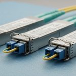
| Connector | LC duplex (common) | Physical mating and polarity | LC-LC patch cords |
| DOM support | CMIS or vendor DOM (platform dependent) | Telemetry and alarm thresholds | DOM-capable SFP+ / SFP28 modules |
| Operating temperature | Commercial (0 to 70 C) or Industrial (-40 to 85 C) | Laser bias stability and compliance | Choose temp grade matching enclosure conditions |
Standards and validation you should reference
At the physical layer, the Ethernet optical interface is governed by the relevant IEEE 802.3 clauses for optical links. For example, 10GBASE-SR is defined in IEEE 802.3, while the actual module behavior is validated via vendor test procedures and compliance documentation. For field readiness, confirm the module’s wavelength class, transmit power range, receive sensitivity, and whether it is rated for the temperature grade you will deploy. For DOM behavior, check your switch firmware release notes, because DOM parsing changes across software versions.
Authority references to keep handy include [Source: IEEE 802.3] and vendor datasheets from the transceiver manufacturer and your switch/router vendor. For additional connector handling guidance, review [Source: ANSI/TIA-568] and fiber cleaning best practices from reputable industry guidance such as [Source: FOA (Fiber Optic Association)] via their published training materials and checklists. IEEE 802.3 standard reference

Selection criteria: a decision checklist engineers actually use
When your Dedicated Interconnect depends on a single optical path, selection must be deterministic. Use this ordered checklist to minimize surprises during installation and acceptance testing.
- Distance and fiber type: measure or verify the run length including patch cords, slack, and any splices; confirm OM3/OM4 vs OS2.
- Wavelength and optics class: ensure the module wavelength matches the fiber design and the provider handoff requirements (for example, 850 nm for SR on multimode, 1310 nm for common SM links).
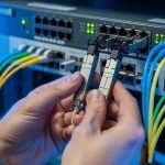
- Data rate and interface standard: match the transceiver to the switch port type (SFP+, SFP28, QSFP+), and confirm the port is provisioned for the expected Ethernet speed.
- Switch compatibility: verify the transceiver is on your platform’s supported list; many switches reject non-compliant modules or misread DOM.
- DOM support and alarm thresholds: confirm your platform reads DOM correctly and that thresholds will not trigger early warnings under normal temperature drift.
- Operating temperature and enclosure airflow: choose the temp grade; in hot aisles, a module rated only for 0 to 70 C can degrade faster.
- Budget and vendor lock-in risk: OEM modules may cost more but reduce RMA churn; third-party can work well if compatibility is proven for your exact switch model and firmware.
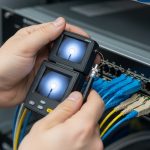
Pro Tip: In many field cases, link bring-up fails not because the transceiver is “wrong,” but because the polarity is reversed on LC duplex patching. Before swapping optics, verify transmit-receive direction end to end and confirm you are using the correct polarity method for your patch panel layout; then re-run optical diagnostics (DOM readings and link counters) after cleaning and reseating.
Real-world deployment scenario: 10G SR on a leaf-spine edge
Consider a mid-size enterprise deploying Dedicated Interconnect for Google Cloud with a 10G handoff to a router acting as the edge. The on-prem design uses a leaf-spine topology in two racks: 48-port 10G ToR switches uplink to spines, and the edge router connects to one spine via a 10G dedicated fiber patch. The physical path from the router to the interconnect cage is 62 meters, using OM4 multimode with LC duplex patch cords and two mechanical splices. In this scenario, engineers typically select a 10GBASE-SR SFP+ transceiver rated for the OM4 distance class, confirm DOM works in the platform, and validate link stability by checking CRC errors and optical power readings after fiber cleaning.
Operationally, the acceptance test should include: verifying link speed is at 10G, confirming transmit power and receive power are within the module’s DOM range, and monitoring interface counters for at least 30 minutes for error bursts during traffic ramp-up. If you see intermittent flaps under load, suspect patch cord damage, insufficient cleaning, or marginal optical power rather than routing.
Common mistakes and troubleshooting tips
Below are frequent failure modes that field teams encounter during Dedicated Interconnect rollouts. Each includes a root cause and a practical fix.
Link does not come up after install
Root cause: Mismatched optics type (for example, SR multimode module used on single-mode fiber) or wrong wavelength band. Another common cause is using an unsupported transceiver form factor or port mode.
Solution: Confirm the module part number and wavelength, then verify the fiber type and cabling plan. Check switch transceiver compatibility and port configuration, then reseat after cleaning the LC connectors with appropriate lint-free wipes and inspection confirmation.
Link flaps or shows high CRC errors
Root cause: Contaminated connector end-faces, damaged patch cords, or reversed polarity on duplex LC connections. Under load, marginal optical budgets show up as receive sensitivity issues.
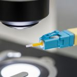
Solution: Inspect with a fiber microscope, clean, and re-terminate only if inspection shows scratches or residue. Re-check polarity and compare DOM receive power against the module’s expected operational window.
DOM alarms, “unsupported transceiver,” or sudden threshold warnings
Root cause: DOM incompatibility between third-party optics and the switch firmware, or a temperature grade mismatch causing laser bias drift. Some platforms enforce DOM compliance and will reduce performance or disable ports.
Solution: Update switch firmware to the version validated for that optics ecosystem, and swap to an OEM or a third-party module explicitly tested with your exact switch model. Ensure airflow and ambient temperature are within the module’s rated operating range.
Cost and ROI note: balancing OEM reliability vs third-party savings
In typical enterprise procurement, a single 10G optical transceiver can range from roughly $40 to $150 depending on brand, wavelength band, and reach class; OEM-branded modules are often higher. The total cost of ownership (TCO) is dominated by failure rates, RMA logistics, and downtime during maintenance windows. Third-party modules can reduce unit cost, but ROI depends on compatibility: if you save $60 per module but spend 6 hours troubleshooting DOM rejection and cleaning rework, the savings can disappear quickly.
Field teams often maintain a small “known-good” inventory: at least one spare per optics class and port type, especially for Dedicated Interconnect edges where maintenance windows are constrained. Record DOM readings and module serials during acceptance so you can correlate future incidents to optical behavior rather than guessing.
FAQ
What does a Dedicated Interconnect transceiver need to match exactly?
At minimum, it must match the Ethernet speed, fiber type, and optics wavelength class expected for the run length. It should also be compatible with your switch or router optics interface and support DOM in a way your platform can read. If any of these mismatch, you may see link failures or error bursts.
Is multimode (850 nm) ever appropriate for interconnect links?
Yes, when the physical distance is within the rated reach for the chosen multimode fiber type, often OM3 or OM4. For longer spans or uncertain attenuation, single-mode OS2 with 1310 nm or 1550 nm is typically safer. Always confirm the run length including splices and patch cords.
Do I need DOM support for Dedicated Interconnect?
Many production switches do not merely “accept” a module; they use DOM to populate telemetry and trigger alarms. If your platform enforces DOM compliance, a module without compatible DOM behavior may be blocked or may generate persistent warnings. Verify with your switch vendor guidance and test on a spare port if possible.
Can I use third-party optics instead of OEM?
Often yes, but you must ensure compatibility with your exact switch model and firmware version. Validate with your vendor’s transceiver matrix or by testing in a non-critical port first. Treat third-party modules as “qualified” only after acceptance tests confirm stable link and acceptable DOM ranges.
How do I troubleshoot high errors after the link is up?
Start with fiber inspection and connector cleanliness, then verify duplex polarity and patch cord integrity. Next, review DOM receive power and optical alarms, and compare them to expected operational ranges. If errors correlate with temperature or time, investigate airflow and enclosure ambient conditions.
What should I check during acceptance testing?
Confirm negotiated speed, monitor interface counters for CRC, symbol, and FEC-related errors (if applicable), and record DOM transmit and receive values. Keep a short monitoring window, such as 30 to 60 minutes, while traffic ramps to the expected baseline. Document module serial numbers for faster incident response.
Choosing the right Dedicated Interconnect transceiver comes down to matching optics and fiber physics to your switch’s operational expectations, then validating with DOM and error counters after cleaning and polarity checks. Next, review fiber link budget and optical power margins to quantify whether your link has enough receiver sensitivity margin for stable operation.
Author bio: I am a field-focused network engineer who has commissioned multiple carrier-style Ethernet handoffs and learned to verify optics with DOM and fiber inspection rather than assumptions. I write from deployment experience to help teams reduce outages during interconnect migrations and upgrades.