Why your high density fiber module plan breaks at scale
When you push a leaf-spine fabric into high density fiber module territory, the bottleneck often is not switching ASIC capacity, but optics integration: power draw, reach mismatch, DOM behavior, and vendor-specific optics signaling. This article helps network architects and field engineers evaluate CXP transceiver modules carrying 12x10G for compact, repeatable deployments in data centers and telecom aggregation rooms. You will get practical selection criteria, a spec comparison table, and troubleshooting steps grounded in how CXP optics behave in real chassis.

Understanding the CXP 12x10G building block
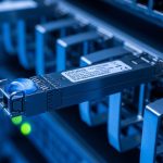
CXP is a multi-lane pluggable form factor designed to pack many optical channels into a single module footprint. For high density fiber module designs, the key advantage is that you can treat a single CXP slot as a 12-channel “optics bundle,” which reduces port sprawl across the chassis and improves cable management. In practice, a 12x10G CXP module maps to twelve independent 10G lanes that your switch fabric routes as separate logical ports.
What “12x10G” implies operationally
Each lane typically targets 10.3125 Gb/s line rate for 10G Ethernet variants (commonly 10GBASE-R). The module’s optical engines and driver electronics must meet link budget requirements across wavelength and reach, while the host cage must support the correct electrical signaling and lane mapping. If your switch expects a specific CXP electrical interface and lane ordering, an optics module that is electrically compatible but lane-mapped differently can produce “link up/down flaps” or persistent errors.
Standards and what to verify
- IEEE 802.3 covers 10GBASE-R physical layer behavior and link characteristics: [Source: IEEE 802.3].
- Vendor datasheets for the CXP module specify optical parameters (wavelength, launch power, receiver sensitivity), DOM implementation (I2C register map), and temperature range: [Source: vendor datasheets].
- Host switch manuals define whether the cage supports CXP optics, which diagnostic thresholds are enforced, and whether DOM is required for port bring-up: [Source: switch vendor hardware guide].
Pro Tip: In high density fiber module builds, treat DOM telemetry as part of your acceptance test. If you deploy without validating DOM register reads and alarm thresholds during commissioning, you can lose hours later to “mystery” link instability caused by marginal optical power or a switch-side threshold that differs from your previous optics batch.
Key specs that determine reach and stability
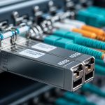
For 12x10G CXP modules, the dominant design variables are wavelength (typically SR around 850 nm for multimode), optical reach (meters), fiber type (OM3/OM4/OM5), connector style (LC is common on breakout harnesses), and power/thermal behavior. Temperature range matters because high density fiber module deployments often run in constrained airflow zones where transceiver temperatures approach vendor limits.
| Spec | Typical CXP 12x10G SR (850 nm) | Typical CXP 12x10G LR (1310 nm) | Typical CXP 12x10G ER (1550 nm) |
|---|---|---|---|
| Data rate | 12 lanes x 10.3125 Gb/s | 12 lanes x 10.3125 Gb/s | 12 lanes x 10.3125 Gb/s |
| Wavelength | ~850 nm | ~1310 nm | ~1550 nm |
| Fiber type | MMF (OM3/OM4/OM5) | SMF | SMF |
| Reach (headline) | ~300 m (OM3) to ~400-500 m (OM4) | ~10 km | ~40 km |
| Connector interface | Breakout harness to LC (varies by vendor) | Breakout harness to LC (varies by vendor) | Breakout harness to LC (varies by vendor) |
| Power consumption | Often higher than single-lane optics; validate per model | Often higher than single-lane optics; validate per model | Often higher than single-lane optics; validate per model |
| Operating temperature | Check vendor range (commonly commercial vs extended) | Check vendor range | Check vendor range |
Because CXP modules can be vendor-specific in thermal design and lane mapping, you should treat the table as a starting point, not a guarantee. Always compare the exact SKU parameters from the module datasheet to the switch’s optical compatibility list.

Selection criteria: a checklist for choosing the right high density fiber module
Engineers typically decide quickly in the early phase, but the best outcomes come from a disciplined checklist that matches your actual deployment constraints. Use the ordered factors below as a go/no-go gate for each CXP 12x10G module SKU.
- Distance and link budget: Confirm whether you need SR (MMF) or LR/ER (SMF). Validate connector losses, patch panel attenuation, and worst-case budget margins for your measured fiber plant.
- Fiber plant type: Verify OM3 vs OM4 vs OM5 if using SR. For SMF, confirm core diameter and any splices introduced during moves/adds/changes.
- Switch compatibility: Confirm the host supports the CXP electrical interface and lane mapping for 12x10G. Rely on the switch vendor’s supported optics list where available.
- DOM behavior: Check whether the module supports DOM (I2C) and whether the switch reads it cleanly. Validate alarm thresholds for low received power and temperature.
- Operating temperature: Match your hottest zone. In dense chassis, transceiver temperature can run near the vendor maximum during peak load; validate with thermal measurements during commissioning.
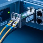
- Connector and harness strategy: Ensure your breakout harness matches your cabling standard and bend radius constraints. High density fiber module builds fail when harnesses are swapped incorrectly.
- Vendor lock-in risk: OEM optics can reduce integration risk, but third-party modules may work if they meet the electrical spec and are validated for your switch. Track failure rates by vendor batch to avoid surprises.
Build vs buy: OEM, certified third-party, or mixed
For high density fiber module projects, mixed sourcing can be viable, but only if you run a structured qualification plan. A common field approach is to start with OEM optics for the first cabinet, then qualify a third-party SKU in parallel using identical fiber runs and the same switch ports. If your environment is mission critical, keep at least one OEM batch in reserve to isolate whether a future fault is optical plant, switch cage, or module electronics.
Common mistakes and troubleshooting that save outages
High density fiber module deployments tend to fail in predictable ways because the physical layout and the optical budget are unforgiving. Below are concrete pitfalls with root causes and fixes you can apply during commissioning and operations.
-
Pitfall 1: “Link up but CRC errors climb within hours.”
Root cause: Marginal launch power or a fiber plant issue (microbends, dirty connectors) that passes initial tests but degrades under thermal cycling.
Solution: Clean connectors with approved methods, re-terminate if needed, and compare DOM reported received power against vendor thresholds. Re-run BER tests at peak load windows. -
Pitfall 2: Persistent link flaps after transceiver insertion.
Root cause: Electrical lane mismatch or unsupported optics signaling for that specific switch hardware revision; sometimes lane ordering differs between vendors.
Solution: Confirm you are using the exact CXP model supported for your switch OS and hardware revision. If you have a spare set, A/B test across identical ports to isolate whether the host cage or module is the variable. -
Pitfall 3: “Works in one cabinet, fails in another.”
Root cause: Airflow differences causing transceiver temperature to exceed the module’s operating envelope, especially in high density fiber module rows with blocked front-to-back flow.
Solution: Measure transceiver temperatures during load. Improve airflow (cable routing, blank panels, baffles) and, if needed, choose modules with extended temperature ratings. -
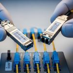
Pitfall 4: Wrong harness orientation or lane mapping during patching.
Root cause: A breakout harness can be visually similar, and fiber strand numbering may not match the port numbering expectation after re-cabling.
Solution: Use a labeling scheme tied to switch port IDs and maintain a harness inventory log. Validate with a single-lane test pattern before scaling patch changes.

Cost and ROI: how to budget for a high density fiber module rollout
Pricing depends on reach class (SR vs LR/ER), vendor, and whether the module is OEM or third-party. As a practical planning range, many teams see OEM 12x10G CXP modules priced in the low hundreds to over a thousand USD per module, while certified third-party options can be lower but require qualification. TCO should include commissioning time, spares inventory, and the operational cost of troubleshooting mismatches.
ROI is not only about unit price. In high density fiber module deployments, reducing the number of cable runs and improving manageability can lower the time cost of moves/adds/changes. However, if third-party optics lead to higher failure rates or increased support tickets, the “savings” can evaporate quickly. Track module performance by batch using DOM telemetry and incident logs so your next refresh cycle is data-driven.
FAQ
What makes a high density fiber module different from standard pluggables?
High density designs typically use multi-lane optics (like CXP 12x10G) so each slot carries many channels. This reduces chassis port sprawl and improves cable management, but it increases the importance of lane mapping, thermal behavior, and switch compatibility.
Can I use third-party CXP 12x10G optics safely in production?
Often yes, but only after qualification on your exact switch model and software release. Validate DOM reads, check for alarm thresholds, and run a stability test over your expected peak temperature and load window.
How do I choose between SR and LR for a high density fiber module plan?
SR (850 nm) is usually best for short reach within the data hall over MMF, while LR (1310 nm) suits longer intra-building runs over SMF. Use measured fiber attenuation and worst-case budget margins rather than nominal reach alone.
What is the most common cause of intermittent errors with 12x10G optics?
Dirty connectors and marginal optical power are frequent causes, especially when initial link verification passes but the system later experiences thermal cycling. Use DOM telemetry, clean and inspect connectors, and re-check patch panel losses.
Do I need DOM support for commissioning?
In many environments, yes. DOM helps you confirm received power trends, temperature, and alarm states so you can catch marginal links early. Even when the link comes up without DOM, operational visibility is still valuable.
Where can I find compatibility guidance?
Start with your switch vendor’s optics compatibility list and the exact CXP module datasheet for DOM and lane mapping. For physical layer behavior, reference IEEE 802.3 as the baseline for 10G Ethernet link expectations: [Source: IEEE 802.3].
If you want a reliable high density fiber module rollout, treat optics selection as a system design problem: fiber plant, switch compatibility, thermal constraints, and commissioning validation all matter. Next, review your cabling standards and connector practices using fiber cabling best practices for 10G and 25G to reduce avoidable link instability.
Author bio: I have deployed multi-lane pluggable optics in data center leaf-spine fabrics, focusing on commissioning automation, optical budget validation, and DOM-based monitoring for stability. I also lead optics and transceiver tech debt reduction programs by standardizing SKUs, harnesses, and failure triage playbooks.