If you are upgrading a data center or metro network and need higher reach or higher spectral efficiency, coherent optics are often the turning point. This article helps network engineers and field technicians plan and commission coherent SFP connectivity across 100G through 1.2T-class links, with practical compatibility checks and failure-mode troubleshooting. You will get an implementation-style checklist, a comparison table of key optical specs, and guidance aligned to IEEE Ethernet optics expectations and vendor interoperability realities. For standards context, see IEEE 802.3 and vendor datasheets for your exact transceiver and DSP/host requirements.
Prerequisites before you install a coherent SFP
Before you touch fiber, confirm the host switch or router supports the coherent optics profile you plan to deploy. Coherent modules are not “just optics”; the DSP, FEC mode, management interface, and power budget must match the line card and optics cage design. Also verify your fiber plant: end-face cleanliness, connector geometry, and link loss at the intended wavelength band affect coherent receiver sensitivity and error rates.
What to gather on-site
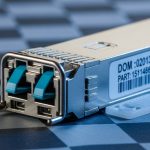
Collect the transceiver part number, DOM capabilities, and operating temperature range from the module label and datasheet. Measure your link budget with the same assumptions the vendor uses for OSNR or receiver sensitivity, not only with average dB loss. Confirm host settings for line rate, modulation (when applicable), and FEC mode; many coherent ecosystems expose these via vendor CLI or auto-negotiation. Finally, stage a known-good patch cord set for quick A/B testing during commissioning.
Expected outcome: You can verify electrical compatibility, DOM availability, and link budget before inserting optics, reducing avoidable link flaps.
Step-by-step commissioning workflow for coherent SFP links
This numbered workflow assumes you are bringing up a coherent optics link between two Ethernet endpoints (switch-to-switch, switch-to-router, or metro transport). While coherent optics are often used with pluggable form factors, the host interface details still matter for stable bring-up.
Validate hardware and firmware alignment
Confirm the host line card firmware supports the coherent module vendor and the targeted speed. For 100G and 200G-class coherent deployments, mismatches in FEC or DSP profiles can cause persistent high BER even when link lights appear normal. If your platform supports optics “type allowlists,” ensure the module vendor and wavelength/variant are approved. Record the host firmware version and the module DOM revision for later audits.
Expected outcome: The module is recognized cleanly by the host with stable status and no repeated DOM read errors.
Clean, inspect, then connect fiber with measured loss
Use an inspection scope to verify connector end-face cleanliness and polish type. Clean with lint-free wipes and approved cleaning tools, then re-inspect. Measure end-to-end link loss with an OTDR or calibrated optical power meter using the same fiber type and expected wavelength band. Coherent receivers are sensitive to not only total loss but also reflections and contamination that increase noise and impair OSNR.
Expected outcome: Optical power and reflectance are within the vendor’s recommended operating conditions.
Configure link parameters and confirm training
Set the port to the intended line rate and ensure FEC settings match both ends. Where the coherent module supports adaptive modulation or vendor-specific profiles, confirm both ends are using compatible settings (often “auto” works, but not always in mixed-vendor environments). Start the link bring-up, then monitor receiver diagnostics such as optical power, temperature, and error counters. Wait for “training complete” indicators if your platform exposes them.
Expected outcome: The link transitions to stable operational state with low error-rate counters over multiple minutes.
Run traffic verification and acceptance testing
Generate sustained traffic using your test toolchain (for example, line-rate frames with a known pattern) and monitor packet loss, CRC errors, and FEC/decoder statistics. Run at least 30 minutes of continuous traffic, then repeat after a controlled re-seat test of the module to ensure the connector interface is reliable. For metro or longer-reach scenarios, also confirm that performance remains stable under typical temperature drift in the rack.
Expected outcome: You can pass an engineering acceptance window with consistent counters and no intermittent retraining.

Key coherent optics specs you must compare
Coherent pluggables vary widely by wavelength band, line rate, reach target, and receiver sensitivity metrics. Even when two modules share “similar” form factors, their DSP configuration and FEC behavior can differ, affecting real-world compatibility and link budget calculations.
Below is a practical comparison of representative coherent pluggable optics used in 100G to 1.2T-class scaling efforts. Use it as a planning reference, not as a promise of interchangeability.
| Spec | Representative Coherent 100G-Class | Representative Coherent 200G-Class | Representative Coherent 400G-Class |
|---|---|---|---|
| Typical line rate | 100G (single-carrier or equivalent) | 200G | 400G (or aggregated) |
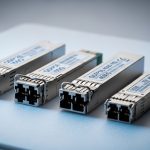
| Form factor | Coherent pluggable (SFP-class or vendor equivalent) | Coherent pluggable (SFP-class or vendor equivalent) | Coherent pluggable (SFP-class or vendor equivalent) |
| Wavelength band | C-band (commonly) | C-band (commonly) | C-band (commonly) |
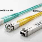
| Connector | LC duplex (typical) | LC duplex (typical) | LC duplex (typical) |
| Reach target | ~80 km to 120+ km depending on OSNR and FEC | ~60 km to 100+ km | ~40 km to 80+ km |
| Operating temperature | 0 to 70 C typical commercial | 0 to 70 C typical commercial | 0 to 70 C typical commercial (verify) |
| Power | Often tens of watts (module-dependent) | Often higher than 100G-class | Highest among these classes; validate host power budget |
For concrete part numbers and baseline specs, consult vendor datasheets and compatibility matrices. Examples of coherent optical ecosystem vendors include [Source: IEEE 802.3] for Ethernet framing expectations and vendor documentation for module-specific DSP and FEC modes. Also see vendor product pages such as coherent transceiver catalogs from mainstream optics suppliers; for general pluggable behavior and DOM interfaces, cross-check with your host vendor’s optics guide. IEEE 802.3 Working Group

Selection criteria checklist for coherent SFP procurement
Engineers typically choose coherent optics using a decision process that balances reach, interoperability, and operational risk. Use this ordered checklist during sourcing and pre-install validation.
- Distance and fiber type: confirm span length, dispersion characteristics, and connector losses; use vendor OSNR or sensitivity targets.
- Speed and FEC profile: verify the module supports the host’s FEC mode and that both ends match.
- Switch compatibility: check the host vendor optics compatibility matrix and supported module revisions.
- DOM and telemetry: confirm DOM availability and which diagnostics your NMS can ingest (temperature, bias currents, optical power, error counters).
- Operating temperature: ensure the module’s rated range covers your rack thermal profile; verify airflow constraints.
- Operating power and cage limits: validate host power budget per slot and airflow; coherent modules can be power-dense.
- Vendor lock-in risk: plan for multi-vendor testing if your procurement policy requires it; mixed-vendor coherent links may require profile alignment.
Expected outcome: You select modules that will train reliably and sustain low error rates under your actual span and thermal conditions.
Pro Tip: In many coherent deployments, the “link up” indicator can appear quickly even when the error correction mode is mismatched. Treat stability as an engineering gate: watch decoder/FEC counters for 20 to 30 minutes under sustained load before declaring success, and only then lock the configuration.
Common pitfalls and troubleshooting for coherent SFP links
Even well-matched hardware can fail due to fiber plant issues, profile mismatches, or host configuration drift. Below are the most common field failure modes with root causes and fixes.
Pitfall 1: Persistent high BER despite “link up”
Root cause: FEC mode mismatch, modulation profile mismatch, or incompatible DSP settings between endpoints. Solution: verify both ends use the same FEC profile and line-rate configuration; if the platform supports it, disable auto-profile and set explicit parameters on both sides, then retest with sustained traffic.
Pitfall 2: Works intermittently after re-seating or cable movement
Root cause: connector contamination, poor seating force, or damaged LC ferrules causing micro-reflections. Solution: inspect with a scope, clean both ends, replace patch cords if the end-face shows scratches or residue, and confirm the module is fully latched in the cage.
Pitfall 3: Receiver alarms during temperature swings
Root cause: module operating temperature outside spec due to insufficient airflow or blocked vents; coherent DSPs can be sensitive to thermal headroom. Solution: check rack airflow, confirm front-to-back direction, measure inlet temperatures, and ensure the module’s rated temperature range covers your environment.

Cost and ROI considerations for coherent SFP deployments
Coherent pluggables typically cost more than direct-detect optics, but they can reduce total span cost by enabling longer reaches per hop. In many operational models, the ROI comes from fewer intermediate sites, reduced patching complexity, and better utilization of existing fiber. As a realistic planning range, coherent optics often fall into the mid-hundreds to low-thousands of dollars per module depending on speed class, reach, and vendor ecosystem; third-party modules can be cheaper, but compatibility testing time and higher failure variance can increase TCO. Always include commissioning labor, spares strategy, and expected failure rates from your supplier SLAs in the business case.
Expected outcome: You understand the trade-off between higher module CAPEX and lower network build CAPEX and operational disruption.
Real-world deployment scenario: leaf-spine with metro reach
Consider a 3-tier data center leaf-spine topology with 48-port 10G/25G ToR switches uplinking to aggregation, plus a metro interconnect from two sites. In this environment, the operator uses coherent pluggables to extend a 100G-class uplink over a 90 km dark fiber span between sites, targeting stable OSNR under seasonal temperature changes. They run the coherent optics at 100G per link initially, then scale bandwidth by upgrading selected paths to 200G and aggregating toward 1.2T-class capacity using additional parallel links. During commissioning, they monitor receiver error counters via telemetry and require a 30-minute sustained acceptance window before declaring the link part of the production traffic set.
FAQ
What makes a coherent SFP different from direct-detect SFP optics? Coherent modules include DSP and support advanced modulation and FEC behavior, enabling longer reach and better tolerance to impairments. Direct-detect modules typically use simpler intensity detection and have shorter