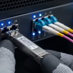
In modern data centers, a transceiver is no longer a “dumb” optical component. When alarms, telemetry, and vendor-specific diagnostics matter, engineers rely on a module management interface to read and control optics safely. This article helps network architects, field engineers, and procurement teams compare CMIS 5.0 advanced control behavior against legacy management approaches and make a practical selection.

CMIS 5.0 module management interface vs legacy control paths
CMIS 5.0 (Common Management Interface Specification) defines how transceivers expose diagnostics and control using an I2C-like management channel and a standardized register map. Compared with older approaches that focused mainly on basic digital diagnostics (temperature, bias current, received power, transmitted power), CMIS 5.0 emphasizes richer telemetry, configuration hooks, and more predictable behavior under automation. In practice, the switch or host system polls the transceiver frequently (often every few seconds to tens of seconds depending on alarm policies) and uses the module management interface to interpret thresholds and status.
Legacy “digital optical monitoring” implementations can still work for many networks, but they often lack the same depth of module identity, calibration metadata, and consistent control semantics. That gap shows up during incident response: engineers may see “Link down” with limited root cause signals, or they may struggle to correlate optical degradation trends across vendors. CMIS 5.0 aims to make those signals more structured and automatable.
What CMIS 5.0 changes operationally
From a field perspective, CMIS 5.0 changes how teams build monitoring and change workflows. Instead of only reading static DOM pages, automation can query capability descriptors, validate module type, and ensure that optical settings align with platform expectations. The module management interface also supports richer interpretation of diagnostic registers, which reduces “guess-and-replace” cycles.
Performance and telemetry: which interface actually improves uptime
Optical performance is still governed by the physical layer (laser driver behavior, receiver sensitivity, dispersion penalties), but the module management interface affects how quickly you detect performance drift and how accurately you can act. With CMIS 5.0, the host can ingest telemetry that supports earlier detection of marginal optics before they fail outright. That matters in high-utilization leaf-spine fabrics where a handful of degraded links can cascade into congestion.
| Spec category | CMIS 5.0 module management interface (typical) | Legacy DOM-style monitoring (typical) |
|---|---|---|
| Management channel | I2C-based module management interface with standardized register model | Vendor or older standardized DOM registers; less uniform semantics |
| Telemetry richness | Richer diagnostics and capability discovery; improved automation readiness | Common parameters (temp, voltage, bias, power), fewer advanced fields |
| Control/config hooks | More structured control and validation workflows (capability-dependent) | Limited control; mostly monitoring and static identity |
| Alarm automation | Better threshold handling and interpretation for orchestration systems | More custom logic per vendor/platform |
| Compatibility effort | Better standard alignment, but still depends on host support | Often “works” but may not integrate cleanly with modern automation |
Pro Tip: If your monitoring platform triggers on “temperature high” but ignores optical trend signals, you will miss early degradation. In CMIS 5.0 setups, engineers often get better incident timelines by alerting on received power slope and bias drift rather than waiting for hard thresholds.
For standards context, Ethernet optics are still defined by IEEE physical layer requirements such as IEEE 802.3 for link behavior; the module management interface is the glue that lets the host interpret optics health consistently. For reference on CMIS concepts, consult [Source: OCP Transceiver Specifications / CMIS documentation]. For host and module register mapping details, rely on the vendor’s CMIS 5.0 datasheets and the switch platform’s optics management guide.
Cost and ROI: what you save when telemetry is actionable
The direct purchase price of a CMIS 5.0-capable transceiver is not always higher, but the total cost of ownership (TCO) can improve when your operational process becomes faster and less error-prone. Field-proven ROI typically comes from reducing truck rolls, shortening mean time to repair (MTTR), and improving inventory decisions. For example, teams that can confidently identify marginal optics via the module management interface can retire at-risk modules during scheduled maintenance windows instead of during outages.
Realistic price bands vary by speed and reach. As a rough planning range, 10G SR optics are frequently priced in the low tens of USD per module in volume, while higher-speed and longer-reach optics can be materially higher. OEM-branded modules sometimes cost 10% to 30% more than third-party equivalents, but third-party options can still be cost-effective if the host fully supports the module management interface behavior and the module’s calibration aligns with expected thresholds. Always budget for qualification testing and a small “compatibility buffer” in early rollouts.
TCO factors engineers should model
- Failure and degradation rates: use historical RMA data and optical power trend logs.
- Operational labor: cost per incident and average time to isolate root cause.
- Monitoring integration: effort to parse and normalize telemetry fields.
- Vendor lock-in risk: how quickly you can switch suppliers if a module management interface implementation changes.
Compatibility and risk: the hidden work behind “it should work”
CMIS 5.0 standardization helps, but compatibility still depends on host firmware and optics management features. Two systems can both “support CMIS,” yet differ in how they poll registers, interpret capability descriptors, or expose telemetry to control-plane automation. That is why engineers validate not just link bring-up, but also alarm semantics, DOM field mapping, and any supported control features under the module management interface.
When choosing modules, verify that your switch or router platform explicitly supports CMIS 5.0 for the specific form factor and speed. Many platforms support basic DOM universally, but advanced CMIS telemetry or control might require a minimum software version. Confirm with vendor release notes and test results, not assumptions.

Concrete module examples to anchor validation
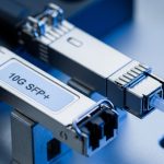
During qualification, engineers often test multiple vendors and compare telemetry. Example optics part numbers you may see in the field include high-volume 10G SR modules such as Cisco SFP-10G-SR, Finisar FTLX8571D3BCL (example family), and FS.com SFP-10GSR-85 (example family). Treat these as reference points for qualification planning; the key is whether your host firmware correctly reads the CMIS 5.0 module management interface registers and maps them to your monitoring stack.
Selection criteria: a decision checklist for the module management interface
Use the following ordered checklist when selecting optics and deciding whether to rely on CMIS 5.0 advanced module control:
- Distance and fiber type: match wavelength and reach to your plant (OM3/OM4/OS2, link budget constraints).
- Data rate and form factor: ensure the module management interface behavior matches SFP, SFP+, QSFP+, QSFP28, QSFP-DD, etc.
- Switch compatibility: confirm the host platform supports CMIS 5.0 telemetry and any control features for your exact software release.
- DOM/telemetry mapping: verify the fields your NMS expects are present and correctly scaled (dBm vs mW, units, calibration offsets).
- DOM support and DOM polling frequency: confirm your automation cadence does not overload the management bus.
- Operating temperature range: align module specs to your ambient conditions and airflow profile.
- Vendor lock-in risk: test at least two suppliers for the same reach class and compare telemetry consistency.
- Documentation and traceability: require datasheets that state CMIS 5.0 support and provide register-level or at least field-level descriptions.
Quick specs comparison for planning
The table below illustrates how engineers compare typical short-reach and long-reach parameters. Always validate with the exact CMIS 5.0 datasheet for your module SKU.
| Parameter | 10G SR (example class) | 25G LR (example class) | 40G/100G LR4 (example class) |
|---|---|---|---|
| Wavelength | 850 nm (multimode) | 1310 nm (singlemode) | 1310 nm band (WDM) |
| Typical reach | Up to ~300 m on OM3/OM4 (varies by class) | Up to ~10 km (varies by class) | Up to ~10 km (varies by class) |
| Connector | LC duplex | LC duplex | LC duplex |
| Operating temp range | Often commercial or industrial (check SKU) | Often commercial or industrial (check SKU) | Often commercial or industrial (check SKU) |
| Management interface impact | Telemetry consistency matters for thresholding and trend alerts | Calibration metadata helps correlate drift with link margin | WDM channel telemetry improves pinpoint diagnostics |
Common mistakes and troubleshooting in module management interface deployments
Even when optics “link up,” engineers can misconfigure monitoring or misinterpret telemetry. Below are frequent failure modes and how to address them.
Alarms never clear or flap
Root cause: threshold units or scaling mismatch between your monitoring system and the telemetry fields exposed via the module management interface. Some stacks convert dBm incorrectly or treat mW as dBm.
Solution: validate one known-good module end-to-end: compare switch CLI/NMS values against the vendor’s expected units. Update your field mapping and confirm that alarm hysteresis is configured.
“CMIS supported” but telemetry fields are missing
Root cause: host firmware may only partially support CMIS 5.0 register sets, or it may require a minimum software version for advanced module management interface features.
Solution: check switch release notes and run a controlled test: insert a module in a spare slot, poll registers at your standard cadence, and confirm that capability discovery returns expected fields.
Link instability after automation changes
Root cause: automation scripts may perform module management interface reads too frequently or attempt unsupported control operations. Excess management polling can increase latency or trigger watchdog behavior in some platforms.
Solution: throttle polling to a safe interval (commonly seconds rather than sub-second), and restrict control actions to documented CMIS 5.0 capabilities. Roll changes with a feature flag and monitor link error counters.

Which option should you choose?
If you are running a standardized automation stack and need consistent telemetry for proactive maintenance, choose CMIS 5.0-capable modules and confirm full host support for the module management interface in your switch firmware. If you operate a small environment with