Nothing derails a rollout like a switch that refuses to bring up links after you swap optics. This article helps network engineers and field technicians confirm Cisco Catalyst transceiver compatible modules using practical, 2024-era verification habits: electrical compatibility, optical parameters, DOM behavior, and operational limits. You will also get a ranked shortlist of the most common module families, plus a checklist that reduces RMA risk and downtime.
Top 8 Cisco Catalyst transceiver compatible optics: how to think about “compatibility”
Compatibility is not just “same connector type.” For Cisco Catalyst platforms, link bring-up depends on speed and optics standard (for example IEEE 802.3 clause-based behavior), optical budget, DOM support, and sometimes vendor-coded EEPROM fields. In a 2024 compatibility matrix approach, engineers treat each transceiver as a system component: optics type plus firmware-coded transceiver parameters plus switch-side port profile. If any of those do not align, you may see link flaps, “unsupported transceiver” events, or negotiated rates that do not match your design.
What to verify in the field (fast)
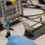
Before you label a module “incompatible,” collect evidence. Check switch logs for transceiver warnings, confirm the port is configured for the expected speed, and verify the fiber type and polarity at the patch panel. For optics, validate that the module wavelength matches the expected fiber plant (for example 850 nm for OM3/OM4 multimode, 1310 nm for many single-mode reach options, and 1550 nm for long-haul). Then confirm DOM readings: temperature, transmit power, and link diagnostics should be within vendor datasheet tolerances.

Top 1: 10G SFP+ SR (850 nm multimode) for predictable short-reach deployments
For many access and aggregation designs, 10G SFP+ SR at 850 nm over OM3 or OM4 multimode fiber remains the most operationally forgiving option. IEEE 802.3 specifies 10GBASE-SR behavior, including nominal optical characteristics and receiver sensitivity assumptions; the switch port typically expects that standard-coded profile from the transceiver. When you use SR modules with the correct DOM and optics parameters, link bring-up is usually fast and stable.
Key specs that matter
- Data rate: 10.3125 Gbps line rate (10G Ethernet)
- Wavelength: 850 nm
- Typical reach: ~300 m on OM3, ~400 m on OM4 (varies by vendor)
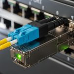
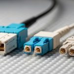
- Connector: LC duplex for most SFP+ SR optics
- DOM: common; temperature and optical power reporting is usually available
- Operating temperature: commonly 0 to 70 C for industrial-free enterprise modules; extended ranges exist
Best-fit scenario
In a 3-tier data center leaf-spine topology with 48-port 10G ToR switches and 2 uplinks per server rack, you may run OM4 trunks from patch panels to top-of-rack. If your measured end-to-end budget shows 2 dB margin after connectors and patch cords, SR modules often provide stable performance without the higher cost of long-reach single-mode optics.
Pros
- Cheaper fiber plant and optics versus single-mode in many sites
- Strong availability of tested module options
- DOM behavior is widely supported
Cons
- Reach limited by multimode bandwidth and installed fiber quality
- Polarity and patch cord type still cause most “it does not link” events
Top 2: 10G SFP+ LR (1310 nm single-mode) when you need more reach
10G SFP+ LR uses 1310 nm single-mode fiber and targets longer reach than SR. This is a common upgrade path when you outgrow multimode or when campus runs use single-mode backbone. Compatibility hinges on the transceiver being coded for 10GBASE-LR and having DOM fields that the Catalyst port can read without strict vendor gating.
Key specs that matter
- Wavelength: 1310 nm
- Typical reach: ~10 km on SMF (vendor-dependent)
- Fiber type: ITU-T G.652.D commonly
- Connector: LC duplex
- Optical power: within class ranges per vendor datasheet
- DOM: often supported
Best-fit scenario
Consider a campus with three buildings connected by a routed core and distributed access. If Building A to B needs 6.5 km and your measured fiber includes 1.2 dB connector losses plus 0.6 dB splice losses, LR optics are frequently the most cost-effective option that still keeps you within budget.

Pros
- Better reach over existing single-mode infrastructure
- Lower sensitivity to multimode bandwidth limitations
- Many validated module ecosystems exist
Cons
- Higher optics cost than SR
- Fiber type mismatch and bad cleaning cause frequent failures
Top 3: 10G SFP+ ER or 1550 nm long-reach options for extended metro links
If you need to span farther across metro-like distances, 10G SFP+ ER style optics at 1550 nm are designed for additional reach. Engineers still treat compatibility as a matrix problem: the switch must accept the transceiver’s coded parameters and DOM behavior, while the optical budget must be validated against attenuation and dispersion assumptions. In practice, ER modules are often reserved for specific links where single-mode reach requirements exceed LR comfort margins.
Key specs that matter
- Wavelength: 1550 nm (ER profile)
- Typical reach: ~40 km (vendor-dependent)
- Dispersion: matters more at longer distances; follow vendor guidance
- Connector: LC duplex
- DOM: usually available
Best-fit scenario
In a metro aggregation network where two sites are separated by 28 km of single-mode fiber, you might run 10G to a small aggregation point. If your OTDR shows 0.22 dB/km average attenuation, the fiber loss alone is about 6.2 dB. With connector and splice losses around 2.5 dB total, ER optics can be chosen to preserve margin while staying within vendor power and receiver sensitivity requirements.
Pros
- Enables long-distance 10G without upgrading to higher-speed gear
- Works well for metro backhaul when fiber is already single-mode
Cons
- More sensitive to dispersion and poor splices over long spans
- Higher cost and more stringent installation discipline
Top 4: 25G SFP28 SR for modern server and ToR upgrades
25G SFP28 SR at 850 nm supports faster uplinks and is increasingly common in server-to-switch and short patch scenarios. For Catalyst deployments, the switch must support 25G on that port and the transceiver must match the expected standard profile. In many cases, operators migrate from 10G SR to 25G SR to increase capacity without changing the fiber plant.
Key specs that matter
- Data rate: 25.78125 Gbps line rate (25G Ethernet)
- Wavelength: 850 nm
- Typical reach: OM4 distances commonly around a few hundred meters depending on module class
- Connector: LC duplex
- DOM: typically supported
- Operating temperature: often 0 to 70 C (check datasheet)
Best-fit scenario
In a rack with 25G NICs and a top-of-rack switch, you may have 120 m from server patch to switch patch panel. If you are using OM4 with clean jumpers and you can document connector counts, a 25G SR module often delivers stable link rates and reduces congestion without moving to 50G or 100G optics.
Pros
- High port utilization efficiency
- Often compatible with existing multimode OM4 designs
Cons
- OM3 may not meet reach expectations at 25G; measure and verify
- More sensitive to link margin than many 10G designs
Top 5: 40G QSFP+ SR4 and 40G QSFP+ LR4 for mid-tier aggregation
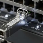
40G QSFP+ transceivers use four lanes. SR4 uses 850 nm multimode; LR4 uses 1310 nm single-mode. Compatibility here is primarily about the QSFP+ cage and the switch’s port profile for 40G, plus DOM and lane mapping correctness. When you select the correct optics family and fiber type, 40G becomes an effective bridge between 10G access and 100G core.
Key specs that matter
- Data rate: 40G aggregated over four lanes
- Wavelength: SR4 at 850 nm, LR4 at 1310 nm
- Connector: often MPO/MTP for SR4; LC for some LR4 variants depending on vendor
- DOM: typically supported
- Temperature: check module class
Best-fit scenario
In an aggregation tier where you connect 16 ToR switches to a pair of aggregation switches, you may need 40G uplinks with ~150 m to patch panels. If your plant uses OM4 with properly keyed MPO cassettes, SR4 can offer a strong balance of cost and performance.

Pros
- Efficient capacity aggregation
- SR4 works well in structured multimode environments
Cons
- MPO polarity and lane ordering mistakes are common
- Some ports require strict optics profile acceptance
Top 6: 100G QSFP28 SR4 vs LR4: choosing the right wavelength and lane strategy
100G QSFP28 optics also use four lanes, but the performance requirements are higher and the operational margin can be narrower. SR4 uses multimode 850 nm; LR4 uses single-mode 1310 nm. For Catalyst compatibility, the module must be recognized as a QSFP28 100G transceiver and the switch must support the specific optics type on that port.
Key specs that matter
- Data rate: 100G over four lanes
- Wavelength: 850 nm for SR4; 1310 nm for LR4
- Connector: MPO/MTP for SR4; often LC for LR4 depending on model
- DOM: common
Best-fit scenario
In a modern data center spine where you connect two core switches using 100G uplinks over single-mode, LR4 modules reduce congestion without requiring a multimode plant upgrade. If your link distance is 2.8 km and the measured loss is within budget, LR4 is often the practical choice for stable operations.
Pros
- Scales bandwidth while keeping port counts manageable
- Lane-based designs map well to structured fiber plants
Cons
- SR4 depends heavily on OM4 quality and MPO handling
- Compatibility varies by Catalyst model and software release
Top 7: 100G QSFP28 CWDM4 or AOC: when fiber availability is limited
When you cannot easily re-cable, some designs use CWDM4 (coarse wavelength division multiplexing over single-mode) or optical active cables (AOC). CWDM4 can reduce the number of fibers needed by using multiple wavelengths; AOC can simplify installation in short runs. Compatibility with Catalyst depends on the specific port type, optics recognition behavior, and the transceiver’s compliance with expected electrical interfaces.
Key specs that matter
- CWDM4 wavelengths: multiple channels across the CWDM grid (vendor-defined)
- Typical reach: commonly a few km to tens of km depending on class
- AOC: limited by reach and power budget; often used for rack-to-rack
- Connector: varies; AOC often uses MPO or proprietary ends
Best-fit scenario
In a retrofit where you must connect adjacent racks but cannot change patch panel layouts, AOC can be deployed for 10G to 100G class links over short distances. For a 30 m run with strict cable tray constraints, AOC can shorten installation time and reduce mechanical connector failures.
Pros
- Fast deployment in constrained spaces
- Reduces connector cleaning errors for short runs (AOC)
Cons
- Higher per-unit cost and vendor-specific behavior
- May have more limited DOM granularity depending on design
Top 8: A practical “Cisco Catalyst transceiver compatible” shortlist: examples and spec checks
Engineers often start with known families and then validate against the 2024 compatibility matrix for the exact Catalyst model and software version. Real-world examples include vendor-coded optics such as Cisco-branded modules and third-party compatible optics that support DOM and standard-coded profiles. Below is a practical comparison table you can use to align wavelength, reach, connector, and operating temperature before you even open the compatibility matrix.
| Module family (example models) | Data rate | Wavelength | Typical reach | Connector | DOM | Operating temperature | Common use |
|---|---|---|---|---|---|---|---|
| Cisco Catalyst SR SFP+ (Cisco-branded) | 10G | 850 nm | ~300 m OM3 / ~400 m OM4 | LC duplex | Yes (typical) | 0 to 70 C (typical class) | ToR and access |
| Cisco Catalyst LR SFP+ (Cisco-branded) | 10G | 1310 nm | ~10 km SMF | LC duplex | Yes (typical) | 0 to 70 C (typical class) | Campus and metro |
| Finisar FTLX8571D3BCL (example third-party SR) | 10G | 850 nm | ~300 m-class OM3 | LC duplex | Yes | 0 to 70 C (check datasheet) | Structured multimode plants |
| FS.com SFP-10GSR-85 (example third-party SR) | 10G | 850 nm | ~300 m OM3 / ~400 m OM4 | LC duplex | Yes | 0 to 70 C (check datasheet) | Cost-optimized SR |
| Cisco SFP-10G-SR (example Cisco-branded SR) | 10G | 850 nm | ~300 m OM3 / ~400 m OM4 | LC duplex | Yes | 0 to 70 C (typical) | Standard 10G SR links |
| 10GBASE-LR style SFP+ modules (vendor variants) | 10G | 1310 nm | ~10 km SMF | LC duplex | Yes (typical) | 0 to 70 C (check) | Single-mode campus links |
Note: exact reach and temperature depend on the specific SKU and datasheet. Always validate against the switch model and the optics compatibility matrix for the Catalyst platform you deploy. For standards context, align with IEEE 802.3 for the relevant Ethernet PHY and transceiver classes. [Source: IEEE 802.3 series]
Pro Tip: In many Catalyst deployments, the fastest path to “true incompatibility vs bad fiber” is to compare DOM transmit power and temperature against the vendor datasheet immediately after insertion. If DOM values are normal but the link fails, the root cause is usually fiber polarity, connector contamination, or patch cord type rather than EEPROM coding. This saves hours of swapping modules during cutovers.
Selection criteria checklist for Cisco Catalyst transceiver compatible decisions
Use this ordered checklist before ordering spares. It is designed to mirror how engineers validate optics in the real world: from physical layer realities to switch acceptance behavior.
- Distance and fiber type: confirm OM3/OM4 vs SMF and measure end-to-end loss, not just nameplate reach.
- Speed and optics standard: ensure the transceiver matches the exact Ethernet PHY (for example 10GBASE-SR, 10GBASE-LR, 25GBASE-SR, 40GBASE-SR4).
- Switch model and software version: verify the Catalyst platform and the port profile; compatibility can vary with release.
- DOM support and behavior: confirm the module provides expected DOM fields and does not trigger switch warnings.
- Connector and polarity handling: LC duplex vs MPO/MTP polarity and lane mapping must match your patching standard.
- Operating temperature and airflow: check module class; ensure intake and exhaust airflow meet the module’s limits.
- Vendor lock-in risk and warranty terms: decide between OEM modules and third-party compatible optics with clear RMA policies.
- Optical budget margin: include connectors, splices, patch cords, and aging assumptions; keep a practical safety margin.
Common mistakes and troubleshooting tips (field-proven)
Even when you pick the right “family,” real failures often come from predictable errors. Below are common pitfalls with root cause and a fix you can execute quickly during maintenance windows.
Wrong fiber type or wrong reach assumption
Root cause: installing 850 nm SR optics into a plant that is actually older multimode with higher attenuation, or using OM3 cabling for a higher-speed SR mode where bandwidth margin is insufficient. The switch may show link up/down or unstable throughput.
Solution: validate fiber type and measure loss with an optical meter or OTDR. Recalculate budget using connector counts and patch cord lengths; replace with the correct optics family (often LR or a different SR class).
MPO polarity or lane ordering mistakes for SR4 and 100G SR4
Root cause: MPO/MTP patching uses polarity schemes, and lane ordering mismatches can prevent link even when the wavelength and reach are correct. Symptoms can include “no link” or repeated link training failures.
Solution: inspect cassette polarity, confirm keying direction, and re-terminate or use polarity-correct jumpers. Verify with a known-good module and a continuity check before re-cabling long runs.
Dirty connectors causing receiver overload or low optical power
Root cause: contamination on LC or MPO endfaces increases insertion loss and can drop received power below sensitivity. DOM may show weak transmit power or abnormal receiver readings.
Solution: clean with appropriate fiber cleaning tools and inspect with a scope. Re-seat optics after cleaning; replace patch cords if you see visible scratches or persistent haze.
Switch port profile mismatch or admin speed configuration
Root cause: port is configured for a speed that does not match the transceiver’s negotiated mode, especially after migrations or template reuse. The transceiver may be fine, but the port is not.
Solution: confirm interface speed/duplex settings and ensure the port supports the transceiver’s intended rate. Align configuration with the switch hardware guide for that Catalyst model.
Cost and ROI note: OEM vs third-party optics in a Catalyst environment
In practice, OEM optics often cost more but reduce