If your long-haul links are showing rising error rates after a wavelength change, temperature swing, or a fiber reroute, the culprit is often chromatic dispersion. This article helps network engineers and fiber techs choose the right chromatic dispersion transceiver approach (and the supporting optics) to stabilize performance over distance. You will get a practical Top list of options, plus a troubleshooting section built around real field failures.
Top 8 ways to handle chromatic dispersion in long-haul optics
Chromatic dispersion (CD) spreads different optical wavelengths over time, effectively broadening pulses and degrading signal-to-noise ratio as distance grows. In practice, you manage it by selecting the right modulation/baud rate, using dispersion-compensating optics, choosing transceivers that match the fiber type, and validating the link budget with vendor and standards guidance like IEEE 802.3 and manufacturer datasheets. The best choice depends on span length, fiber type (SMF vs NZ-DSF), and whether you can tune wavelength or must lock to a fixed grid.
CD-robust coherent transceivers (DSP-heavy) for 100G/200G/400G
For many operators, the cleanest solution is to use coherent optics with DSP that can tolerate (and compensate) dispersion digitally. A good field pattern is deploying coherent transceivers on long-haul routes where you cannot guarantee uniform fiber plant or where channels are dynamically provisioned. You still need to respect limits: if the span is too long or the baud rate too high for the fiber’s dispersion coefficient, DSP can only do so much.
Key specs to watch include symbol rate/baud rate, supported channel spacing, and the transceiver’s specified dispersion tolerance (often tied to a launch power and receiver sensitivity). Also check whether your switch/router line card supports that coherent form factor and whether the optics are tuned for standard ITU-T grids.
Best-fit scenario: a service provider moving from 10G to 100G on a mixed plant where some spans are 70–90 km of standard single-mode fiber (SMF) and others are newer low-slope fiber. Coherent optics reduce “surprise” outages during re-lighting because DSP handles residual dispersion across operating temperature.
- Pros: strong tolerance to dispersion and polarization effects; better margin with variable plant
- Cons: higher cost; requires compatible coherent line cards; must validate power levels carefully
Fixed-wavelength high-performance optics matched to SMF dispersion
If your network is stable—same fiber route, same wavelength plan, and relatively consistent launch conditions—then fixed-wavelength transceivers can be a cost-effective way to control CD impact. The idea is simple: pick the wavelength and optics class that minimize CD penalties for your specific fiber’s dispersion slope and coefficient. This is common in enterprise WAN where you have a known partner circuit and want predictable optics.
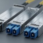
Key specs to watch: center wavelength (for example, 1310 nm vs 1550 nm windows), any specified dispersion penalty, and the transceiver’s allowed input power and receiver overload thresholds. Even with “fixed” optics, temperature drift can slightly shift wavelength, so you should confirm the transceiver’s wavelength stability range in the datasheet.
Best-fit scenario: a campus WAN with 20–40 km spans on SMF where the operator uses 1310 nm optics for reach and 1550 nm optics for longer routes. If you know your dispersion map and you keep launch power within spec, CD issues become manageable without adding external dispersion compensation.
- Pros: simpler operations; often lower TCO than coherent
- Cons: less forgiving to fiber changes; requires tight adherence to wavelength plan
Dispersion-compensating transceivers or external modules (DCM/DCF) for hard spans
When you have a fixed modulation scheme and you must push a long span where CD dominates, dispersion-compensating approaches are direct and effective. You can implement CD compensation using transceiver-integrated solutions (less common) or external dispersion compensating modules inserted in the optical path. In the field, many teams use external modules when they need to swap fiber types or adjust CD compensation dynamically without replacing transceivers.
Key specs to watch: compensation range (in ps/nm), insertion loss (in dB), reflectance/return loss behavior, and connectorization (LC vs SC). Insertion loss matters because it directly reduces your optical budget and can push you into receiver sensitivity failure if you are already near the margin.
Best-fit scenario: a long-haul metro link with spans around 100 km where you cannot switch to coherent and the modulation format is fixed. You add DCF-based compensation modules so the effective dispersion over the span is near zero at the operational wavelength.
- Pros: predictable CD correction; works with many fixed-rate systems
- Cons: extra loss; more components to fail; careful optical budget math required
Narrow-linewidth DFB/EML optics with better wavelength stability
Chromatic dispersion interacts with wavelength accuracy: if your laser drifts, the effective dispersion over the span changes. Narrow-linewidth DFB or EML-based optics can reduce that risk, especially in systems operating near dispersion slope boundaries or where channel spacing is tight. This option is often overlooked because engineers focus on “reach,” but wavelength stability can be the difference between stable eye diagrams and intermittent BER spikes.
Key specs to watch: linewidth (or spectral purity), wavelength tolerance, and side-mode suppression ratio (if specified). Also check whether the transceiver supports digital diagnostics (DOM) so you can correlate temperature and bias changes with performance events.
Best-fit scenario: a route with temperature cycling due to outdoor cabinets or exposed splice cases. Using optics with stronger wavelength stability and monitoring helps you catch drift before it becomes a service-impacting CD penalty.
- Pros: reduces wavelength-induced dispersion variation; easier than adding extra modules
- Cons: still not a full compensation solution; may not save you on extremely long spans
Choosing the right fiber type: SMF vs NZ-DSF vs G.652/G.655/G.654
Sometimes the “transceiver” answer is actually a fiber plant answer. If you can choose or standardize the fiber type, you can reduce CD and CD slope effects across the wavelengths you use. NZ-DSF (non-zero dispersion-shifted fiber) is designed to keep dispersion non-zero at certain wavelengths, which can help with nonlinearities while still giving manageable CD behavior for coherent or fixed-rate systems.
Key specs to watch: dispersion coefficient (ps/nm/km), dispersion slope, and attenuation (dB/km) for the specific fiber category. In the field, I’ve seen performance improve simply by standardizing on a specific ITU-T fiber class along a route segment, then matching transceiver wavelength plans to it.
Best-fit scenario: a carrier upgrading a route where some spans are older G.652 SMF and others are newer fibers. Standardizing to a compatible fiber strategy reduces CD surprises during upgrades.
- Pros: long-term fix; improves consistency across multiple transceiver generations
- Cons: requires construction work; not always feasible for existing routes
Baud rate and modulation format selection (lower symbol rate reduces CD penalty)
Higher baud rates increase sensitivity to dispersion because pulses broaden faster relative to the receiver’s ability to recover timing. If your vendor supports multiple modulation formats, you can trade capacity for stability by lowering symbol rate or switching formats that are less CD-sensitive. This is a classic “engineering knob” that often beats adding extra optical hardware.
Key specs to watch: supported modulation formats (for example, DP-QPSK vs higher-order schemes), symbol rate, and channel spacing constraints. Always confirm the vendor’s CD tolerance curves or link design guides; don’t rely on marketing reach numbers.
Best-fit scenario: a 200G deployment where a specific channel fails only during seasonal temperature changes. Lowering the symbol rate or adjusting the modulation format can restore margin without touching fiber or adding DCF modules.
- Pros: no extra insertion loss; can be done via provisioning
- Cons: reduced throughput; depends on line card and optics support
DOM-driven monitoring and alarm thresholds tied to dispersion events
DOM (digital optical monitoring) won’t “fix” chromatic dispersion by itself, but it helps you keep the link inside safe operating windows. In the field, CD-related outages often correlate with temperature-induced laser drift, launch power changes, or aging-induced sensitivity degradation. With DOM, you can set alarms on TX bias, laser temperature, received power, and sometimes optical diagnostics that indicate drift.
Key specs to watch: which DOM parameters are exposed (laser temperature, bias current, TX power, RX power), update rate, and whether the platform supports thresholding and syslog/SNMP events. I like to correlate DOM logs with OTDR or fiber inspection results and with any provisioning changes.
Best-fit scenario: a multi-tenant metro network where channels move between sites. DOM alarms help quickly detect when a particular transceiver is out of its stable thermal regime, before BER spikes turn into tickets.
- Pros: faster detection; helps prevent repeat outages
- Cons: requires good monitoring discipline; alarms without action plans can be noisy
Validate with real link design: OSNR, launch power, and dispersion maps
Engineers sometimes buy a “better transceiver” when the real issue is incorrect link design assumptions. For CD-heavy links, you need a proper dispersion map (including fiber type per span), correct launch power settings, and an OSNR approach for coherent systems. For intensity-modulation/direct-detection, you still need accurate optical budgets and penalty terms that include dispersion.
Key specs to watch: launch power range, receiver sensitivity, safety margins, and whether your design tool accounts for fiber dispersion slope and polarization mode dispersion (PMD). Cross-check against vendor link design tools and relevant standards like IEEE 802.3 and ITU-T recommendations for optical system planning: see IEEE 802.3.
Best-fit scenario: any time you are changing wavelength plans, adding inline amplification, or rerouting around a damaged splice case. A quick re-run of the link design can prevent a costly optics swap.
- Pros: prevents wrong purchases; improves predictability
- Cons: requires accurate fiber inventory and disciplined measurements

Chromatic dispersion transceiver comparison: what engineers actually buy
Below is a practical comparison of common long-haul approaches you might see in the field. Exact reach varies by vendor, modulation, baud rate, and the fiber’s dispersion coefficient and slope, so treat this as a decision-starting point, not a guarantee. For authoritative compatibility and limits, always check the transceiver datasheet and your line card’s supported optics list.
| Option type | Typical data rate | Common wavelength window | Reach ballpark | How it helps CD | Connector / form | Temp range (typ.) | Power / complexity |
|---|---|---|---|---|---|---|---|
| Coherent DSP transceiver | 100G to 400G | C-band (around 1550 nm) | ~80 to 200+ km per span (depends on design) | Digital compensation (DSP) for residual CD | Varies: coherent pluggable + LC | -5C to 70C (vendor-dependent) | Higher power; higher BOM |
| Fixed-wavelength high-performance optics | 10G to 100G | 1310 nm or 1550 nm | ~40 to 80 km (IM/DD dependent) | Matches CD profile by wavelength choice | SFP+/QSFP form factor, LC/SC | 0C to 70C (common) | Lower power; simpler ops |
| Dispersion-compensating module | IM/DD or fixed-rate coherent | Depends on wavelength | Span-dependent; adds loss | Analog CD correction via DCF/DCM | Inline module + patch cords | -5C to 75C (varies) | Extra insertion loss; more components |
| Narrow-linewidth DFB/EML optics | 10G to 100G | C-band / L-band | ~40 to 100 km (system dependent) | Reduces wavelength drift impact on CD | SFP+/QSFP form factor, LC | -5C to 70C (vendor-dependent) | Mid complexity; moderate cost |
Concrete examples you might encounter when shopping (always confirm compatibility with your platform): Cisco coherent optics often come as line-card specific modules; for fixed optics, common vendor families include 10G SR/LR optics (not typically CD-focused) and specialized long-haul variants. If you are looking at third-party pluggables, check DOM support and optical power class. For reference on typical transceiver part naming and optical specs, see vendor datasheets like [Source: Cisco Transceiver Modules Datasheets] and [Source: FS.com Transceiver Datasheets].

Selection checklist for a chromatic dispersion transceiver (field order of operations)
Here’s the exact order I’d use when choosing the right chromatic dispersion transceiver approach for a long-haul span. If you skip steps, you usually end up buying the wrong optics or overcompensating and losing receiver margin.
- Distance and span count: measure actual span lengths and confirm where the fiber type changes (use fiber inventory, OTDR traces).
- Fiber dispersion parameters: identify dispersion coefficient and slope for the fiber class (SMF vs NZ-DSF, plus any legacy sections).
- Modulation format and baud rate: lower symbol rates generally reduce CD penalty; verify supported modes on your platform.
- Transceiver wavelength plan: confirm center wavelength and channel grid alignment; check wavelength stability specs.
- Switch/line card compatibility: verify supported optics list and required transceiver type (especially for coherent).
- DOM support and thresholds: ensure your platform reads the DOM fields you need for operational monitoring.
- Optical budget math: include insertion loss for any inline dispersion-compensating module and account for connector/splice losses.
- Operating temperature and airflow: outdoor cabinets and hot aisles shift laser temperature; confirm transceiver temperature range and derating guidance.
- Vendor lock-in risk: price out third-party options, but validate DOM behavior and compatibility to avoid intermittent issues.
Pro Tip: In many CD-related incidents, the root cause is not “too much distance” but “too much margin drift.” A transceiver that is within spec during commissioning can cross a CD-sensitive threshold after a patch-cord change, a connector re-termination, or an amplifier gain adjustment shifts launch power by a couple dB. Always re-run the link budget after any optical change, even if the hardware stays the same.
Common mistakes and troubleshooting tips (what causes real failures)
Let’s talk about the failure modes I see during long-haul maintenance, and how to fix them without guessing.
Ignoring dispersion slope and mixing fiber types
Root cause: link calculations assume a single fiber type, but the route includes mixed segments (for example, SMF plus a different dispersion-slope fiber). Residual CD then becomes wavelength-dependent, causing some channels to fail while others seem fine.
Solution: update your dispersion map per span, then re-run the vendor link design tool or your internal model. If you cannot standardize fiber, consider coherent DSP or wavelength plan adjustments.
Overlooking insertion loss from dispersion-compensating modules
Root cause: engineers add DCM/DCFs to reduce CD but forget that these parts add insertion loss. The link budget may still pass “on paper” but fail under aging, connector contamination, or higher-than-expected splice loss.
Solution: measure actual RX power after installation, clean connectors, and verify margin against receiver minimum sensitivity. If margin is tight, reduce other losses first (patch cords, splitters, dirty bulkheads) or adjust amplifier gain.
Misaligned wavelength grid or wrong channel provisioning
Root cause: channel provisioning points the transceiver to a frequency grid slot that does not match the dispersion assumptions. This shows up as intermittent BER increases, often clustered around certain channels.
Solution: confirm the ITU-T grid/channel plan, verify the transceiver’s intended center wavelength, and check whether the line card uses the same grid as the planning spreadsheet. Use DOM and platform telemetry to confirm actual operating wavelength when available.
Laser thermal drift not correlated to performance logs
Root cause: temperature changes shift laser wavelength and output power. Without DOM correlation, teams chase “random” BER spikes caused by CD sensitivity changes.
Solution: enable and export DOM telemetry, then correlate TX temperature/bias and RX power with error counters. If you see strong correlation, improve cooling or replace optics with tighter wavelength stability specs.

Cost and ROI note: what to expect in real budgets
Pricing varies wildly by data rate and ecosystem lock-in, but here are realistic ranges from typical procurement cycles. OEM coherent optics and line-card specific modules often cost far more than fixed-rate optics; dispersion-compensating modules add extra parts and labor, plus ongoing inventory overhead for spares. Third-party chromatic dispersion transceiver options can cut purchase cost, but you must factor compatibility risk: DOM field mapping, firmware expectations, and occasional “works until it doesn’t” behavior after platform upgrades.
Rule of thumb ROI: If CD issues are causing frequent truck rolls or extended downtime, paying for more robust optics (or coherent DSP) can pay for itself quickly by reducing failure frequency. If you have stable plant conditions and good monitoring, fixed-wavelength optics plus disciplined link-budget changes can be the cheapest path with lower TCO.
FAQ: chromatic dispersion transceiver buying questions
Do I need a chromatic dispersion transceiver, or is fiber tuning enough?
Sometimes fiber type and wavelength plan are the real fix, especially if the route mixes fiber categories. But if you cannot control the plant or you need flexibility across channels, coherent DSP optics or dispersion-compensating modules can be the safer operational choice.
How do I know whether CD or something else is causing BER spikes?
Correlate BER/errored seconds with wavelength changes, temperature, and launch power. If OSNR or receiver margin drops at the same times as fiber plant changes, CD and power budget issues are likely; also check for connector contamination and polarization-related effects.
Will DOM alarms tell me dispersion is the problem?
DOM usually