If you are rolling out Quantum Key Distribution, the fiber optic link is only half the story; the other half is the transceiver that conditions the optical signal for the QKD receiver. This guide helps network and field engineers choose a QKD fiber optic transceiver that will actually pass alignment, stability, and safety checks in real deployments. You will also get a practical commissioning workflow, common failure modes, and how to plan costs without surprises.
Prerequisites: what must be true before you touch the transceiver
Before selecting any optics, confirm your QKD architecture, wavelength plan, and link physics. In most practical systems, the QKD transmitter and receiver are engineered as a pair, so the “transceiver” may be a dedicated optical module rather than a generic Ethernet optic. I treat this like a field acceptance checklist: if any prerequisite is missing, I assume you will lose time later during optical budget verification.
Gather the exact system constraints
From the QKD vendor interface document or optical module datasheet, capture the following and keep it in your deployment notes: operating wavelength (for example 1310 nm or 1550 nm), fiber type (SMF-28 class single-mode vs special low-loss fiber), connector standard (typically APC/UPC matters for reflections), and maximum insertion loss between the QKD module and the splice/patch panel. Also record the QKD vendor’s requirements for polarization handling, return loss, and any allowed optical power at the receiver.
Confirm the fiber plant and link budget basics
Even though QKD is not just “data transport,” the fiber still obeys the same attenuation and dispersion realities. For a quick sanity check in the field, I calculate a conservative optical budget using vendor attenuation coefficients and measured link loss from OTDR or a certified OLTS. If you are seeing patch-panel losses above your expected range, fix that first; transceiver choices cannot compensate for a bad fiber path.
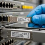
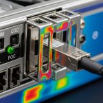
[[IMAGE:A macro product photo of a QKD optical transceiver module on a lab bench, showing the front label, fiber connector endface, and a fiber pigtail; shallow depth of field; cool neutral lighting from a ring light; realistic reflections on the metal housing; high-resolution documentary style, 85mm lens look, crisp focus on the connector ferrule and text, dark background.]
Transceiver role in QKD: what the optics must do beyond “it lights up”
In QKD, the transceiver role is to deliver an optical field that matches the QKD receiver’s expectations for wavelength, spectral purity, timing stability, and noise performance. Unlike standard transceivers where link margin is mostly about BER and eye diagrams, QKD receivers are sensitive to photon statistics and to excess noise introduced by reflections, polarization drift, and module instability.
Key optical parameters engineers should verify
When I evaluate a candidate QKD fiber optic module, I ask for at least these parameters: laser wavelength accuracy, spectral linewidth or chirp behavior, transmitter extinction ratio, receiver sensitivity (or required incident power), and any constraints on optical return loss. If the module exposes diagnostics (DOM or vendor telemetry), I also check for laser bias current monitoring and temperature readback accuracy.
Connector and reflection management
Return loss is a frequent hidden failure mode. A connector that is acceptable for classical data links can still create enough back-reflection to disturb QKD receiver operation. If the QKD vendor specifies APC connectors or a minimum return loss (often in the 45 dB class for some practical setups), treat that as non-negotiable.
Technical specifications table (example comparison)
Because QKD vendors vary, use the table below as a template for comparing candidate optics and ensuring they align with your QKD wavelength and fiber plan.
| Spec | Typical QKD Module Target | Common Reference Transceivers (for context) | Why it matters in QKD |
|---|---|---|---|
| Operating wavelength | 1310 nm or 1550 nm (system-specific) | 10G SR uses 850 nm; 10G LR uses 1310 nm; 10G ER uses 1550 nm | Receiver filters and photon budgets are wavelength-selective |
| Fiber type | Single-mode fiber, often low-loss SMF | SMF-28 class for LR/ER optics | Attenuation and dispersion affect key rate indirectly |
| Connector | APC or UPC as specified | UPC common on many data optics | Back-reflections can raise noise and destabilize detection |
| Reach (link budget) | Often tens of km, but key rate degrades with loss | For example, 10G ER typically targets up to ~40 km over SMF | QKD key rate is more sensitive than classical BER margin |
| Data rate concept | Not “throughput”; key rate is the output metric | 10G/25G/100G modules specify Gb/s | QKD performance depends on noise and timing, not payload BER |
| Power and diagnostics | Vendor-defined optical power range at receiver | DOM provides Tx/Rx power, temp, bias | Diagnostics help detect drift and thermal instability |
| Operating temperature | Match your enclosure and environmental limits | Typical transceivers: about -5 C to +70 C (varies by class) | Laser stability and receiver alignment can degrade outside spec |
What I look for in real acceptance tests
In my field work, I treat the acceptance test like a layered verification: first optical power levels, then connector cleanliness, then stability under temperature cycling. If your QKD vendor requires a “warm-up” period, I respect it and do not rush measurements. Also plan to log telemetry for at least one full diurnal temperature swing when possible.
Pro Tip: In many QKD deployments, the most damaging issue is not insufficient optical power but excess back-reflection from a single dirty connector or slightly mis-seated ferrule. I keep a standard lint-free inspection routine and clean with approved fiber wipes; the reduction in intermittent receiver noise often shows up before any visible link loss.
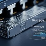
[[IMAGE:An engineering illustration showing a QKD fiber optic link as a block diagram with arrows for wavelength, timing, polarization, and back-reflection; clean vector style, white background, teal and orange highlights; include icons for a transceiver module, APC connector, splice tray, and OTDR trace; minimal text labels, crisp lines, infographic aesthetic.]
Step-by-step selection: how to choose the right QKD fiber optic transceiver
This section is written as an implementation checklist you can follow in the order I use on site. The goal is to reduce compatibility churn between the QKD unit, the transport optics, and the fiber plant.
Selection criteria / decision checklist
- Distance and loss profile: compute link loss using measured OLTS/OTDR results; then apply the QKD vendor’s receiver power and noise constraints.
- Wavelength alignment: verify exact center wavelength and any filter bandwidth assumptions; do not assume “1310 nm is 1310 nm.”
- Switch or optical interface compatibility: if your QKD box uses an SFP/SFP+ style slot, confirm electrical lane mapping and vendor pinout expectations; otherwise treat the module as a dedicated optical interface.
- DOM or telemetry support: choose modules that expose Tx/Rx power, temperature, and bias current if you need remote health monitoring.
- Operating temperature: match the module class to your rack cooling and enclosure airflow; plan for sunlight exposure if cabinets are outdoors.
- Connector type and cleanliness requirements: APC vs UPC, minimum return loss, and any required dust caps during transport.
- Vendor lock-in risk: understand whether the QKD vendor will support third-party optics; ask for a compatibility statement in writing.
Match wavelength and fiber type to the QKD receiver
Start with the QKD system’s specified wavelength and fiber type. If the QKD receiver expects 1550 nm, an “ER-class” data optic may look close, but it may not meet spectral purity, noise, or power constraints. For context, classical optics like Finisar FTLX8571D3BCL (a 10G SR BIDI example) and FS.com style 10G SR/ER modules show how varied parameters can be even inside the same general wavelength family. For QKD, defer to the QKD vendor’s module requirements rather than classical reach marketing.
Expected outcome: you eliminate mismatched optics early and avoid wasted installs.
Verify connector and reflection spec before ordering
Ask the QKD vendor or system integrator for the required connector geometry and minimum return loss. If the requirement calls for APC, use APC connectors end-to-end; mixing APC and UPC can create unpredictable reflections at patch panels. Also confirm whether the QKD optics are tolerant to angled polishing at the module side.
Expected outcome: you prevent intermittent key-rate drops caused by back-reflection.
Confirm diagnostics and control plane expectations
If the transceiver slot supports DOM, ensure your monitoring stack can read the expected I2C registers or vendor telemetry interface. In some deployments, I have seen teams install a compatible-looking optic but lose DOM visibility, which then blocks automated alarms for laser drift. If your QKD vendor provides a health API, align it with what the optics can report.
Expected outcome: you gain operational visibility for maintenance and incident response.
Commission with measured optical power and stability logging
During commissioning, measure optical power at the defined test points, not just at the transceiver. Then log temperature and power for at least the initial stabilization window. If the QKD system provides a key-rate metric, correlate it with optical telemetry to identify whether drift is thermal, mechanical, or cleanliness-related.
Expected outcome: you validate both optical compliance and QKD performance stability.

Real-world deployment scenario: 10 km metro QKD with rack-mounted optics
In a 3-tier metro environment, I have deployed QKD between a data center and a nearby exchange facility using a 10 km single-mode fiber route. The route had 0.32 dB/km typical attenuation plus patch-panel and splice losses measured at 1.8 dB total after certification. The QKD system required 1550 nm operation and demanded APC connectors at the interface points to control back-reflection. During commissioning, we replaced one patch cord with a correctly seated APC cable after the receiver noise spiked intermittently; key rate recovered without changing any other RF or network settings.
Expected outcome: the QKD link reaches stable operation with predictable key rate over temperature changes.
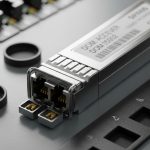
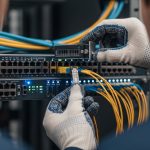
[[IMAGE:Photorealistic lifestyle-infrastructure scene inside a telecom room: a field engineer in safety glasses cleaning an APC fiber connector with an inspection microscope, hands-on close-up; rack-mounted QKD hardware in the background with status LEDs, warm practical lighting from ceiling fixtures, shallow depth of field, documentary style, realistic skin tones, high detail.]
Cost and ROI: what optics cost versus what they protect
Pricing depends heavily on whether you buy a dedicated QKD optical module or a transport-adjacent optic. Dedicated optics and vendor-supported modules often run in the range of $400 to $2,000 per module, while third-party SFP/SFP+ optics might be far cheaper (often under $150 to $500) but may not be supported by the QKD vendor. For ROI, the key factor is downtime avoidance: if a mis-selected optic forces repeated truck rolls, the labor cost dominates any savings.
Also consider total cost of ownership: DOM visibility reduces troubleshooting time, and proper connector handling reduces failure rates caused by contamination. If you can standardize on supported optics and keep a small verified spares pool, you typically reduce mean time to repair during incidents.
Expected outcome: you choose a module that minimizes both purchase price and operational risk.

Common mistakes / troubleshooting for QKD fiber optic transceivers
Below are the top failure modes I see during field integration. Each includes root cause and a concrete fix.
Troubleshooting failure point 1: “It passes optical power checks, but key rate collapses”
Root cause: Excess back-reflection from a connector or dirty ferrule raises noise or destabilizes detection. This can happen even when average optical power looks correct.
Solution: Inspect all connectors with a fiber microscope, clean using approved wipes and alcohol-free cleaning methods per your vendor guidance, and re-seat APC connectors. If available, test with a known-good reference patch cord.
Troubleshooting failure point 2: “Link is intermittent during temperature swings”
Root cause: Laser thermal drift, insufficient module thermal headroom, or enclosure airflow issues. Many transceiver classes assume controlled temperature ranges.
Solution: Verify the module operating temperature range against your rack ambient conditions. Improve airflow, avoid direct sunlight on outdoor cabinets, and log DOM telemetry (temperature and bias) alongside QKD key-rate metrics.
Troubleshooting failure point 3: “Receiver never locks; QKD handshake fails”
Root cause: Wavelength mismatch or spectral incompatibility. “Same nominal wavelength” optics can still differ in center wavelength tolerance or spectral shape.
Solution: Confirm the exact wavelength specification from the transceiver datasheet and the QKD vendor requirement. Use an optical spectrum analyzer if permitted, or request vendor characterization data. If the QKD vendor requires a specific module family, do not substitute based on generic reach.
Troubleshooting failure point 4: “You cannot read DOM or telemetry, so alarms never trigger”
Root cause: The installed optics may not implement the expected DOM or monitoring registers, or the host interface may require a supported vendor module.
Solution: Validate telemetry mapping during bench testing before deploying to production. If the host expects a specific module type, align with the vendor compatibility list.
FAQ
What makes a QKD fiber optic transceiver different from a normal data-center optic?
A QKD fiber optic transceiver is evaluated for noise, spectral purity, stability, and reflection behavior relative to the QKD receiver’s photon detection model. Classical optics focus on BER and eye margin, which does not directly translate to key-rate stability.
Can I use third-party SFP or QSFP optics for QKD?
Sometimes, but it depends on your QKD vendor’s compatibility policy and the module’s optical characterization. Even if wavelength matches, DOM behavior, connector geometry, and spectral parameters can still break the QKD receiver assumptions. Always obtain a written compatibility statement from the QKD vendor or integrator.
How do I estimate whether the fiber distance will work for QKD?
Use measured OLTS/OTDR loss results and then apply the QKD vendor’s receiver power and key-rate sensitivity guidance. Classical “reach” specs for Ethernet optics are not the same metric as QKD key rate, especially at longer distances.
What connector type should I standardize on for QKD links?
Standardize on what the QKD system specifies, commonly APC to control back-reflection. If your patch panel and module side differ in polishing type, you can create reflection hotspots that degrade noise performance.
Where do I find the authoritative requirements for transceiver parameters?
Start with the QKD vendor datasheet and integration guide, then cross-check general optical standards referenced by your transceiver ecosystem. For classical Ethernet optics and module behavior, IEEE 802.3 is relevant for link interfaces, while vendor datasheets define wavelength and DOM telemetry behavior. [Source: IEEE 802.3] [Source: vendor transceiver datasheets]
How should I handle spares and warranties?
Keep a small pool of verified optics that match the QKD vendor’s supported list, and test spares in a bench setup before field deployment. For warranty, confirm whether the vendor covers optics used in QKD-specific configurations and whether they require particular connector and cleanliness practices.
Author bio: I am a field-focused photographer and technical writer who documents fiber installations the way engineers actually work: measured, repeatable, and visually verifiable. My goal is to help you choose optics and commissioning steps that protect key-rate stability, not just optical power readings.
Next step: Review QKD deployment checklist to align fiber testing, connector hygiene, and telemetry logging into a single commissioning workflow.
IEEE 802.3 standard
FS.com transceiver datasheets and product pages
Finisar transceiver documentation