When a link aggregation group (LAG) looks healthy but throughput stalls or packet drops appear after a transceiver swap, the root cause is often optical mismatch rather than LACP itself. This article helps network engineers and field technicians design and troubleshoot bonded fiber links using LACP with fiber transceivers. You will get practical selection criteria, a real deployment example, and failure-mode troubleshooting that maps to how modern switches hash traffic across member links.
How LACP hashes traffic across bonded fiber links

LACP (IEEE 802.1AX) forms a logical bundle from multiple physical links, but it does not “stripe” a single flow across members. Instead, most switches use a hash (often based on L2/L3 headers such as source/destination MAC, IP, and sometimes TCP/UDP ports) to decide which member carries each flow. In practice, this means bonded fiber links improve aggregate capacity when you have many concurrent flows, but a single heavy stream may still be limited by one member.
Operationally, you want each member link to present consistent link characteristics to avoid uneven error rates and link flap events. On the optics side, that usually means matching wavelength, optical class, and receive sensitivity behavior across all transceivers in the bundle. Vendor implementations vary, so you should confirm the switch’s LAG hashing algorithm and whether it includes VLAN tags or L4 ports in the hash. If you are using MLAG or stacked chassis, confirm that the hashing domain is the same across the member ports.
What to verify on the switch before touching optics
- Confirm LACP mode: active/active or active/passive, and that the ports are in the same LAG.
- Check member state: each port should be in selected state (not suspended) and show consistent speed/duplex.
- Validate hashing inputs: note whether VLAN ID is included; misalignment can shift flows between bundles.
- Confirm no STP or ERPS interference: a “blocked” member can create confusing partial behavior.
Fiber transceiver requirements for stable bonded fiber links
For bonded fiber links, the optics must behave like matched “lanes” from the perspective of link training, link monitoring, and error reporting. Under IEEE 802.3, most Ethernet PHYs run standardized signaling and manage link bring-up, but the transceiver’s analog performance still matters: transmit power, receiver sensitivity, and jitter tolerance affect bit error rate (BER) and how quickly modules declare link instability.
In the field, I typically treat transceivers in a LAG as a single procurement line item: either all OEM modules from the same vendor family or all third-party modules that are explicitly validated for the same switch platform. Mixing module generations can introduce differences in DOM (Digital Optical Monitoring) scaling, alarm thresholds, and internal laser bias behavior, which can trigger err-disabled ports or excessive CRC errors.
Key specs to compare across members
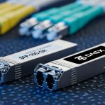
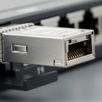
At minimum, compare wavelength, reach class, data rate, connector type, and temperature range. For SFP/SFP+ and QSFP families, confirm the module type matches the port wiring expectations (SR vs LR vs ER) and that the transceiver supports the exact interface data rate (for example, 10G vs 25G). Also check DOM support: many switches use DOM thresholds to take action when optical power drifts.
| Parameter | Example: 10G SR SFP+ | Example: 25G SR SFP28 | Example: 100G SR4 QSFP28 |
|---|---|---|---|
| Nominal wavelength | 850 nm | 850 nm | 850 nm |
| Reach class | Up to 300 m (OM3/OM4 depending on vendor) | Up to 100 m (typical OM4; verify datasheet) | Up to 100 m (typical OM4; verify) |
| Connector | LC duplex | LC duplex | LC duplex (4-lane internal optics) |
| Data rate | 10.3125 Gbps (10G Ethernet) | 25.78125 Gbps (25G Ethernet) | 103.125 Gbps (100G Ethernet) |
| Power consumption | ~0.8 W to 1.5 W (varies) | ~1.0 W to 2.0 W (varies) | ~3.5 W to 5 W (varies) |
| Operating temperature | 0 to 70 C or -40 to 85 C variants | 0 to 70 C or -40 to 85 C variants | 0 to 70 C or -40 to 85 C variants |
| DOM | Commonly supported (read Tx/Rx power, alarms) | Commonly supported | Commonly supported |
When you select optics for bonded fiber links, treat connector cleanliness and fiber type as part of the optical “spec.” A “compatible” module on a dirty connector can still produce elevated error counters and periodic link resets, which will look like an LACP instability.
Pro Tip: If your LAG uses a hash that keys on L4 ports, a few long-lived TCP sessions can pin traffic to a single member link. During acceptance testing, generate multiple parallel flows (for example, a stream per client) so you can observe member utilization balance and detect optical problems that only surface when one member carries more load.
Real-world deployment: bonded fiber links in a leaf-spine data center
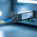
In a 3-tier data center leaf-spine topology with 48-port 10G top-of-rack switches uplinking to spine switches, we built bonded fiber links with LACP across four 10G ports per ToR. Each uplink used 10G SR SFP+ optics at 850 nm over OM4 multimode fiber, with member links configured as a single LAG to the spine pair. The design goal was to deliver up to 40 Gbps aggregate per ToR uplink bundle while maintaining sub-second failover when a link member dropped.
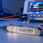
We standardized on the same transceiver family across all member ports, aligned DOM thresholds, and validated optics against the switch vendor compatibility list. During commissioning, we measured optical Tx/Rx power using DOM and compared it to baselines: members with Rx power near the vendor’s lower limit showed higher CRC counts after connector remating. Cleaning LC endfaces and re-terminating a single suspect patch improved error rates immediately, and LACP member selection remained stable during a controlled link pull test.
That experience reinforced an operational truth: LACP can only react to what the PHY reports. If one member link has a higher BER due to optics or fiber damage, it may still stay “up” while accumulating errors, degrading performance long before it fully fails.
Selection checklist for bonded fiber links with transceivers
Before ordering replacement optics for bonded fiber links, run a structured checklist. This avoids the common scenario where the LAG is correct but the modules are not truly interchangeable on that platform.
- Distance and fiber type: confirm reach calculations for OM3/OM4/OS2 using the module datasheet and your actual patch cord length and loss budget.
- Data rate and interface: ensure the module matches the port speed (10G, 25G, 40G, 100G). Do not assume “downspeeding” is safe.
- Connector and polarity: LC duplex polarity and consistent transmit/receive direction matter, especially when patching is reworked.
- Switch compatibility and vendor lock-in risk: check the switch model’s transceiver support list and note whether it blocks unknown optics or applies stricter DOM alarms.
- DOM support and thresholds: verify the module exposes Tx/Rx power and alarm flags in a way the switch interprets correctly.
- Operating temperature range: if the rack has poor airflow, prefer -40 to 85 C options for margin, and measure actual module temperature if your platform reports it.
- Batch consistency: buy in the same lot where possible; mixing lots can shift laser bias and affect BER headroom.
- Failover behavior expectations: confirm LACP timers (fast vs slow) and how quickly the platform removes a member under loss of signal.
Compatibility caveats that matter during swaps
- Some platforms treat DOM mismatches as warnings, others as hard errors that trigger port disable.
- Not all “SR” modules are equal: vendors publish different launch power and receiver sensitivity targets, which changes margin.
- For multi-lane optics (for example, SR4), unequal lane power can still pass link but increase errors; monitor the platform’s lane-level diagnostics if available.
Common mistakes and troubleshooting for bonded fiber links
Most LAG issues get blamed on LACP, but optical transceiver and fiber problems are common. Below are concrete failure modes I have seen in audits and onsite repairs.
Mixed optics in the same LAG member set
Root cause: Members use different transceiver models (even if both are “10G SR”), leading to different Tx/Rx power levels, DOM alarm behavior, and BER margin. Under load, the weaker member accumulates CRC errors and can intermittently lose signal.
Solution: Replace optics so all members use the same model number and vendor family. Confirm DOM readings are within expected ranges and run a sustained traffic test while monitoring CRC and link flaps.
Dirty or mis-polarized connectors after maintenance
Root cause: LC endfaces are contaminated or patched with reversed polarity during a cabling change. The link may come up due to forgiving power levels, but error counters rise, and LACP member selection can become erratic if the platform treats excessive errors as link quality degradation.
Solution: Inspect with a fiber microscope, clean with approved wipes and isopropyl alcohol where appropriate, then re-seat and verify polarity with a continuity tester. Re-check optical power after cleaning.
Assuming LACP will load-balance a single heavy flow
Root cause: Hashing pins a single traffic flow to one member link. A “stuck” throughput symptom can look like a bad transceiver even though the optics are fine; member utilization remains uneven.
Solution: Validate hashing behavior by generating multiple flows (different source ports or destination addresses) and confirm traffic spreads across members. Only after that should you correlate optics to CRC or error counters.
Ignoring temperature and airflow constraints
Root cause: In high-density racks, optics can overheat, causing laser power drift and increased BER. The failure may appear only during peak hours.
Solution: Improve airflow, verify rack temperature, and choose modules with an appropriate operating range. Use DOM to trend Tx bias and Rx power over time.
For deeper reference on LACP behavior, consult [Source: IEEE 802.1AX] and your switch vendor’s LAG configuration guide. For optical electrical/optical performance expectations, use the module datasheet and relevant Ethernet PHY guidance such as [Source: IEEE 802.3].
Cost and ROI: OEM vs third-party optics for bonded fiber links
In typical enterprise and colocation environments, OEM transceivers often cost more per module than third-party equivalents. Realistic street pricing varies by speed and reach, but a common pattern is: 10G SR SFP+ modules may run roughly in the low tens of dollars to higher depending on brand and temperature grade, while 25G SFP28 and 100G QSFP28 SR optics can cost significantly more. Third-party optics can reduce upfront spend, but the ROI depends on failure rates, compatibility friction, and the time you spend validating DOM thresholds and switch behavior.
For bonded fiber links, the total cost of ownership (TCO) includes labor for swaps, downtime risk, and the operational overhead of maintaining a compatibility matrix. If your platform is strict about transceivers, OEM can reduce incident probability. If your environment is stable with proven third-party modules, you can still achieve strong ROI, but only after a controlled pilot that monitors BER proxies like CRC counts and link flaps under load.
FAQ
Do bonded fiber links require identical transceiver models on every member?
In practice, yes. Even if both modules are “SR” at the same wavelength, different vendor families can shift optical power and DOM behavior, increasing CRC risk and making troubleshooting harder. Aim for the same part number across all member ports.
Will LACP ever split one TCP flow across multiple members?
Most LACP implementations do not stripe a single flow across members; they rely on hashing to choose one member per flow. If you need faster per-flow performance, consider application-level parallelism or adjust hashing inputs if your platform supports it.
How can I tell whether the issue is optics or hashing?
Monitor CRC errors, link flaps, and DOM Tx/Rx power per member while generating test traffic. If only one member shows escalating CRC counts or falling Rx power, optics or fiber are likely. If errors are uniform but throughput is uneven, hashing behavior is the likely cause.
What fiber cleaning and polarity checks should I do before blaming hardware?
Inspect endfaces with a fiber microscope, then clean both ends using approved procedures. Verify polarity and continuity after any patch changes, and re-check optical power after reseating. This resolves a large fraction of “mystery” LAG instability reports.
Are DOM readings reliable across different transceiver brands?
They are useful, but not always directly comparable across brands. DOM scaling and alarm thresholds can differ, so treat trends within the same module family as your primary signal, and always compare to vendor guidance.
What is the safest approach for expanding bonded fiber links later?
Procure transceivers that match the existing part number and lot when possible. If you must introduce a new model, pilot it in one member link first, then monitor CRC and link stability during peak load before scaling to the full bundle.
If you want bonded fiber links to behave predictably, standardize transceivers, validate optics margin, and confirm how your switch hashes traffic in LACP. Next step: review the cabling and transceiver model selection workflow in fiber transceiver compatibility checklist.
Author bio: I have deployed and diagnosed LACP and fiber optics in live data centers, including optical budget validation with DOM and BER-adjacent metrics. My work focuses on practical field procedures that reduce downtime during link upgrades and transceiver swaps.