You are wiring a distributed fiber network where every link must light up on the first try, yet budgets and vendor options pull in opposite directions. This article shares best practices for selecting SFP transceivers across distance, temperature, and switch compatibility, helping network engineers, field techs, and data center operators avoid costly rework. You will get concrete specs comparisons, deployment scenarios with real port counts, and troubleshooting patterns tied to common failure modes.
Top 8 best practices for SFP selection that actually work
Think of an SFP not as a part number, but as a contract between optics, electronics, and the fiber plant. The best practices below are field-tested in distributed sites where contractors swap modules quickly, but link performance must remain stable for months. I will reference IEEE Ethernet optical standards and vendor datasheets where they define the behavior you must plan for. Source: IEEE 802.3
Match optics wavelength and reach to your fiber plant
Start with the physical reality: fiber type, measured attenuation, and the expected worst-case loss budget. For 10G Ethernet over multimode, 850 nm SFP+ modules are commonly rated for distances such as 300 m to 400 m, depending on link parameters; for 1310 nm single-mode, reach can extend to kilometers. Confirm whether your plant is OM3, OM4, or single-mode, and whether you have splices and patch panels adding loss. Source: FS.com transceiver documentation
Quick reach sanity check
In practice, I treat the vendor “rated reach” as a ceiling, then subtract margin for aging and test uncertainty. If your OTDR shows 3 dB extra loss across patch runs, do not plan to operate at the edge of the SFP’s receiver sensitivity. For safety, target link budgets with at least 2 to 4 dB headroom after connector and splice losses.
Best-fit scenario: You are connecting remote cabinets across a campus using OM4 patch cords and want predictable 10G behavior. Choose 850 nm multimode SFPs when your measured loss supports it, and document the fiber type in your change ticket.
- Pros: Fewer marginal links, faster acceptance testing
- Cons: Wrong wavelength can cause total link failure
Compare data rate and electrical interface: don’t mix generations
SFP selection is only “plug and play” when the electrical signaling and Ethernet framing align with the switch. A 1G SFP will not carry 10G Ethernet, and even within 10G, your switch might require specific variants such as SR versus LR. I have seen field crews install the correct optics type but the wrong data rate, leading to link flaps that look like optics faults. Always verify the port can support the transceiver’s speed and mode in the switch’s transceiver compatibility list.
Standards and practical checks
For 10GBASE-SR and 10GBASE-LR, vendor optics must meet IEEE 802.3 requirements for optical parameters and management behavior. Use the switch vendor’s “supported modules” list when available, and validate with a short test run before deploying across all sites. Source: IEEE 802.3
Best-fit scenario: You are upgrading a distributed network from 1G to 10G on select uplinks. Use a staged approach: confirm switch firmware supports the module type, then roll out in batches.
- Pros: Eliminates speed mismatch and reduces truck rolls
- Cons: Compatibility lists can lag behind third-party inventory
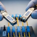
Use a specs comparison table to avoid “looks compatible” traps
When you compare SFPs, you must read the fine print: wavelength, reach, connector type, DOM support, supply voltage class, and operating temperature. Different vendors can publish similar reach while differing in receiver sensitivity, power consumption, and thermal margins. The table below is a practical baseline for common 10G SFP choices you might deploy in distributed fiber networks.
| Example SFP Model | Standard / Data Rate | Wavelength | Reach (typical) | Fiber Type | Connector | DOM | Operating Temp |
|---|---|---|---|---|---|---|---|
| Cisco SFP-10G-SR | 10GBASE-SR / 10.3125 Gb/s | 850 nm | ~300 m class | OM3/OM4 | LC | Supported (per platform) | Commercial / Industrial varies by listing |
| Finisar FTLX8571D3BCL | 10GBASE-SR | 850 nm | ~300 m class | OM3/OM4 | LC | Supported | Commercial |
| FS.com SFP-10GSR-85 | 10GBASE-SR | 850 nm | ~400 m class (varies) | OM4-focused | LC | Often supported | Commercial / extended options |
| Finisar FTLX1311D3BCL | 10GBASE-LR | 1310 nm | ~10 km class | Single-mode | LC | Supported | Commercial |
Best-fit scenario: You are standardizing a mixed fleet across regional sites and want a consistent procurement spec. Use a table like this in your RFP so procurement and engineering speak the same language.
- Pros: Faster comparisons, fewer surprises in thermal and DOM behavior
- Cons: Vendor reach claims assume specific test conditions

Verify DOM and telemetry expectations before rollout
Digital Optical Monitoring (DOM) is how your network “sees” the transceiver: laser bias current, received power, temperature, and sometimes supply voltage. In distributed networks, DOM enables proactive replacement when optical power drifts, preventing silent degradation. But DOM support can vary by switch platform and firmware, and some modules may present DOM data in a way the switch expects differently. Treat DOM as an operational requirement, not a bonus.
Field deployment detail
In a typical operations runbook, I require that the switch reports DOM thresholds and alarms in a dashboard or logs. For example, if received optical power falls below the configured low threshold for a sustained window (such as 5 to 15 minutes), you trigger a maintenance ticket. This reduces outages caused by marginal fibers or connector contamination.
Best-fit scenario: You operate remote substations with limited on-site time and want early warning rather than reactive swaps.
- Pros: Earlier detection of aging optics and fiber issues
- Cons: DOM alarm thresholds may need tuning per module vendor
Respect the operating temperature and ventilation realities
Distributed cabinets can run hot: sunlight on enclosures, blocked vents, or seasonal HVAC failures. SFPs have operating temperature ranges, and the internal laser and receiver electronics respond to thermal stress. Choose industrial-grade or extended temperature modules when ambient conditions exceed typical switch-room norms. Always check the module datasheet for temperature range and derating guidance.
Best-fit scenario: You place switches in outdoor cabinets where ambient can swing widely; you want the link to survive summer heat spikes and winter cold starts.
- Pros: Reduced latent failures and fewer link drops
- Cons: Industrial optics can cost more upfront

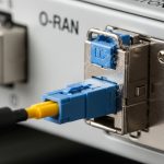
Confirm connector cleanliness and mating geometry (LC is unforgiving)
Many “bad transceiver” cases are actually dirty connectors. LC ferrules collect dust, and even micro-scratches can elevate insertion loss enough to push the receiver near its sensitivity limit. In field practice, I implement a connector cleaning step before swapping modules: inspect with a fiber microscope, clean with approved lint-free supplies, and re-test. Do not use improvised materials that leave residue.
Operational habit
When you replace an SFP, treat the connector interface as part of the failure domain. If you clean and retest, you can often distinguish optics defects from contamination. If DOM shows low received power and the fibers were recently disturbed, clean first.
Best-fit scenario: You are integrating new patch cords in a busy staging area and want to prevent avoidable link loss.
- Pros: Higher success rate on first install
- Cons: Requires microscopes and a disciplined cleaning SOP
Choose OEM versus third-party with a measurable risk model
OEM modules can offer tight compatibility with the switch vendor’s firmware and support channels, but they may cost more. Third-party modules can reduce acquisition costs, yet they introduce risk around DOM behavior, transceiver vendor-specific quirks, and support escalation delays. The best practices here are about governance: require datasheet evidence, run a burn-in test, and track failure rates by vendor lot.
Cost & ROI note: In many markets, 10G SR SFPs often fall into an approximate range of $50 to $200 each depending on brand and temperature grade, while OEM equivalents can be higher. Over a year, the ROI depends on your failure rate and downtime cost: if a marginal optic causes a remote site outage, the labor and truck roll can outweigh the price difference quickly. Track TCO using power consumption (typically a few watts per module), replacement frequency, and labor time.
- Pros: Better procurement flexibility and cost control
- Cons: Support and compatibility may require extra validation
Use a staged acceptance test and document a repeatable checklist
Before you scale across dozens of sites, perform a controlled acceptance test: verify link up, measure received power, confirm DOM alarms, and validate stability under normal traffic patterns. For distributed networks, I recommend a staged rollout: pilot two sites, then expand. Document measured parameters so the next engineer can compare “good” optics metrics against “failing” ones.
Pro Tip: In the field, the most predictive metric is often the received optical power trend from DOM over days, not the one-time link status. A link that stays up while RX power slowly drifts toward the threshold is frequently a connector contamination cycle or a fiber micro-damage that will eventually fail.
Common mistakes / troubleshooting patterns that waste time
Even seasoned teams stumble when optics selection becomes a scavenger hunt. Below are concrete failure modes I have seen repeatedly, with root causes and fixes you can apply immediately.
-
Mistake: Installing the correct wavelength but wrong fiber type (OM3 vs OM4 assumptions).
Root cause: Vendor reach claims assume specific modal bandwidth and test conditions; your plant loss exceeds the module budget.
Solution: Re-measure with OTDR or certified loss testing; switch to the correct optics spec (or reduce distance with patching). -
Mistake: Assuming DOM is identical across vendors and firmware versions.
Root cause: Switch may not parse DOM fields consistently or may apply thresholds incompatible with the module’s calibration behavior.
Solution: Validate DOM readings in the staging switch first; set thresholds based on observed good readings. -
Mistake: Swapping transceivers without cleaning LC connectors after a link drop.
Root cause: Dust or residue increases insertion loss; the receiver becomes marginal.
Solution: Inspect with a fiber scope, clean with approved tools, then retest; only replace optics if RX power remains abnormal after cleaning. -
Mistake: Ignoring temperature grade in outdoor or poorly ventilated cabinets.
Root cause: Thermal stress reduces laser output and increases bit errors; links may flap seasonally.
Solution: Use extended temperature modules and improve cabinet airflow; log temperature and DOM trends.
Selection criteria checklist for distributed SFP deployments
When procurement and engineering meet in the same room, this ordered checklist prevents most avoidable rework. Use it for each link class you standardize, not just for one-off installs.
- Distance and link budget: Use measured fiber loss and connector/splice counts; keep 2 to 4 dB margin.
- Wavelength and fiber type: Confirm multimode (OM3/OM4) versus single-mode; match 850 nm SR or 1310 nm LR appropriately.
- Switch compatibility: Verify port speed, optics type support, and transceiver compatibility list for the exact switch model and firmware.
- DOM support and telemetry: Confirm the switch reports DOM and that alarms behave as expected.
- Operating temperature: Choose commercial or industrial/extended temperature based on cabinet ambient and ventilation.
- Connector and optics interface: Ensure LC geometry matches your patch cords and cleaning SOP exists.
- Vendor lock-in risk: If you must use OEM, plan spares and lead times; if using third-party, run pilot validation and track failures by vendor lot.
- Acceptance testing plan: Define what “good” looks like (link stability window, DOM thresholds, and received power ranges).
Summary ranking: best practices by impact
Not all best practices carry equal weight. The table below ranks what tends to move the needle most in distributed fiber networks, where distance variability and operational constraints amplify risk.