In production and deployment, optical links can look “up” while still carrying enough bit errors to quietly degrade application performance. This article explains how a BERT fiber test is used to determine pass/fail acceptance for common transceivers, and how to set test conditions so the result is defensible to operations, QA, and vendors. It helps network engineers and field technicians who need repeatable methods for optics validation in data centers and enterprise fiber plants.
Why a BERT fiber test is the acceptance test for optics
A bit error rate test uses a known PRBS pattern (pseudo-random bit sequence) sent through the link and measures received errors over a defined observation time. Unlike link-level counters (which may only indicate link up/down), BER testing directly quantifies bit errors and maps them to an error rate target such as 1E-12 or 1E-15, depending on the system class. The underlying physics is that modulation noise, reflections, chromatic dispersion, connector contamination, and receiver sensitivity all manifest as sampling errors that accumulate into measurable BER.
For optical transceivers, BER testing is also the most common way to verify that the module meets the system receiver budget under real cabling conditions. In practice, teams run the test at the transceiver’s rated wavelength and speed, using a patch-cord and a launch condition that approximates deployment. For standards context, the general Ethernet optical performance framework references link quality and optical power/penalty constraints aligned with IEEE 802.3 optical requirements, while BER test practice is documented across telecom test methodology literature and vendor field guides. anchor-text: IEEE 802.3 optical link requirements
Pro Tip: When you see “reasonable” BER but intermittent application issues, do not only chase average power. Test at the same PRBS mode and with the same optical launch condition you used during acceptance; small differences in patch-cord length and connector cleanliness can shift penalty enough to turn a stable BER into bursts that counters miss.
BER testing for optical transceivers: what pass or fail actually means
“Pass/fail” depends on the BER target, the PRBS sequence, the lane rate, and the measurement confidence. In a field acceptance workflow, you typically define: (1) the required BER threshold (example: 1E-12 for interim acceptance, 1E-15 for stringent burn-in), (2) the observation time or number of bits tested, and (3) the allowed “near zero” behavior (for instance, zero errors observed over a defined bit count). Many test sets report either an estimated BER from error counts or a “no error detected” upper bound based on the bits acquired.
Common BER targets tied to practical Ethernet deployments
In modern Ethernet optics, the acceptance threshold is often set by the system’s forward error correction (FEC) mode and the receiver’s expected performance margin. Even when a link uses FEC, BER testing remains valuable because it can reveal marginal analog conditions that may reduce FEC headroom. In deployments without FEC, the link budget must directly support the BER requirement at the receiver.
While exact acceptance criteria are contract- and platform-specific, field teams frequently align test thresholds to system design targets and vendor guidance. For example, some manufacturing and QA processes use 1E-12 or 1E-15 as measurable gates at the module’s rated data rate, with PRBS31 for many Ethernet PHY test workflows. Always obtain the specific criteria from the vendor datasheet, the integrator acceptance plan, or your internal test specification.
Technical specifications table: typical BERT setup parameters
Below is a practical parameter set you can use as a starting point for typical 10G to 100G-class optical modules. Your exact values must match the module and the transceiver test fixture.
| Parameter | Typical value (field acceptance) | Why it matters |
|---|---|---|
| Data rate | 10.3125G (10G class), 25.781G (25G), 53.125G (50G), 64.9G (100G class with lane mapping) | BER is rate-dependent; wrong rate invalidates the test. |
| PRBS pattern | PRBS31 (common), or PRBS9 for some legacy modes | Different patterns stress different receiver behaviors. |
| Observation window | 10^9 to 10^12 bits (or fixed time such as 60s to 300s) | Determines confidence and BER resolution. |
| Pass/Fail threshold | 1E-12 or 1E-15 (project-defined) | Maps error counts to an acceptability target. |
| Optical interface | LC/UPC or MPO/MTP for multi-lane modules | Connector type affects insertion loss and cleanliness. |
| Wavelength | 850nm (SR), 1310nm (LR), 1550nm (ER/LR with single-mode) | Wavelength mismatch invalidates the receiver budget. |
| Operating temperature | Match vendor spec; validate at 0 to 70C or -40 to 85C where required | Receiver sensitivity and laser bias shift with temperature. |

Field procedure: running a BERT fiber test with defensible results
A defensible BERT fiber test is not just “run and see errors.” It is a controlled measurement with documented launch, PRBS configuration, and optics handling. In a field environment, the fastest way to fail acceptance is to skip optical cleanliness steps or use inconsistent patch cords, which changes insertion loss and reflection. The goal is to isolate transceiver performance from cabling and handling variability.
Step-by-step workflow engineers use
- Verify module identity and configuration: Confirm part number and speed/duplex mode. For example, a vendor SFP+ SR module such as Cisco SFP-10G-SR or FS.com SFP-10GSR-85 should be tested at the module’s rated lane rate.
- Inspect and clean connectors: Use microscope inspection and cleaning tools before insertion. Contamination can introduce micro-reflections that increase error bursts.
- Set up the correct test mode: Configure PRBS (commonly PRBS31), lane mapping, and enable the BERT receiver. Ensure the test set and the transceiver agree on signal polarity and encoding mode.
- Control launch and channel conditions: Use a calibrated test fixture and known patch-cord length. Record fiber type (OM3, OM4, OS2), connector type, and total end-to-end length.
- Measure and record: Run for the required observation window. Record error counts, measured BER estimate, and any “loss of lock” or receiver alarm events.
- Decide pass/fail: Apply your acceptance threshold and confidence criteria. If the test set reports “no errors detected,” record the upper bound based on bits tested.
Example transceiver classes and relevant specs
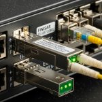
For short-reach multimode, teams often test at 850nm with OM3/OM4 fiber and LC connectors. For single-mode, test at 1310nm or 1550nm depending on the module family. Common examples include Finisar-style optical engines and enterprise SFP/SFP+/QSFP transceivers such as FTLX8571D3BCL (850nm class) or FS.com equivalents like SFP-10GSR-85, where datasheets provide receiver sensitivity and typical power levels that inform your expected margin. anchor-text: Cisco SFP module datasheet example

Comparison: choosing the right test confidence for different link types
Not all BER tests are equal. A short observation window at a low BER target can produce a “pass” that is statistically weak, while a long window at a high BER target can be impractical for field operations. Engineers therefore adjust observation time and error-rate confidence to match the link’s risk profile and the acceptance threshold.
What changes between SR, LR, and multi-lane modules
For multimode SR optics, connector cleanliness and patch-cord quality frequently dominate the error behavior. For long-reach single-mode, laser bias drift and fiber plant reflections can dominate. For multi-lane modules (for example, 40G/100G optics), lane skew, lane-specific power differences, and MPO polarity handling can create lane-dependent errors that appear as overall link degradation.
Test set and measurement limitations to account for
Some BERT instruments support specific PRBS modes and lane configurations. If your transceiver uses a different line coding or requires a specific interface mode, the BERT might not lock properly, leading to false “no data” conditions. Also, “zero errors” depends on the number of bits acquired; your acceptance plan must specify the minimum bits or minimum time.
Pro Tip: For multi-lane optics, validate lane alignment by running the BERT in a mode that reports per-lane error counts if supported. A single bad lane can still pass an aggregate BER calculation if the test set averages across lanes.
Selection criteria checklist for BER pass/fail acceptance
When deciding how to run a BERT fiber test for optical transceivers, engineers typically follow an ordered checklist to reduce disputes and rework.
- Distance and fiber type: Confirm the fiber class (OM3/OM4/OS2) and total length against the module’s rated reach.
- Data rate and PRBS mode: Use the same lane rate and PRBS pattern specified by the acceptance plan or vendor test guidance.
- Switch or host compatibility: Validate that the host switch supports the module’s electrical interface and optics mode (SR vs LR, DOM behavior, and any required breakout configuration).
- DOM support and alarms: Check digital optical monitoring (DOM) for TX bias, TX power, and temperature. DOM does not replace BER, but it helps explain failures.
- Operating temperature conditions: Test at the deployment temperature window; receiver sensitivity can shift with temperature, especially for marginal links.
- Budget and test throughput: Choose observation windows that meet confidence targets without blocking field schedules.
- Vendor lock-in and spares strategy: Track part numbers and optics vendors used in your fleet; repeated acceptance criteria reduce procurement risk.
Common mistakes and troubleshooting tips during BERT fiber tests
Even experienced teams encounter repeatable failure modes. Below are common mistakes, likely root causes, and practical solutions.
“Pass” with intermittent real-world packet loss
Root cause: Test used an insufficient observation window, producing “no errors detected” without statistical confidence for the true BER. Solution: Increase bits tested or time-on-test until the BER upper bound is below your acceptance threshold.
Errors only on one lane in multi-lane optics
Root cause: MPO/MTP polarity inversion, lane mapping mismatch, or one lane’s connector contamination. Solution: Verify MPO polarity, re-seat connectors, and run per-lane BER if your BERT supports it; clean and inspect each ferrule.
BER fails after swapping patch cords, even with same length
Root cause: Patch cord insertion loss differences, unknown fiber grade, or connector geometry variation. Solution: Standardize patch cords in a test kit, verify with OTDR or insertion-loss measurement where possible, and document exact patch cord part numbers.
Loss of lock or unstable PRBS sync
Root cause: Wrong PRBS mode, incorrect interface configuration, or signal polarity mismatch. Solution: Confirm test mode settings, check polarity and encoding compatibility, and ensure the BERT is configured for the transceiver’s expected line rate.

Cost and ROI: what BER testing changes in total cost of ownership
In most deployments, the cost driver is not the BERT instrument itself (usually owned by QA or centralized test teams), but operational time, spares handling, and rework caused by acceptance ambiguity. Third-party transceivers and OEM modules can both be acceptable, but ROI depends on whether you can reproduce BER results under a consistent test procedure. Typical module pricing varies widely by speed and reach: enterprise 10G SR optics may cost in the tens of dollars, while 25G/40G/100G optics can range from low hundreds to higher depending on vendor, temperature grade, and single-mode complexity.
From a TCO perspective, the main savings come from preventing “marginal optics” from being installed where they fail early. A disciplined BERT fiber test approach can reduce truck rolls by catching issues at the bench. However, be realistic: if your acceptance criteria are too strict, you may reject modules that are actually fine for the host platform, increasing procurement cost and inventory churn.
FAQ
What BER target should I use for a BERT fiber test?
Use the BER target defined by your acceptance plan, vendor guidance, or contract. Common field thresholds are 1E-12 and 1E-15, but the correct value depends on FEC usage, risk tolerance, and the observation window you can support.
How long should I run the BERT to claim “pass”?
Duration depends on the bit rate and the required confidence. Your acceptance document should specify minimum bits or minimum time so that a “no errors detected” result has a meaningful upper bound on BER.
Does DOM data replace BER testing?
No. Digital optical monitoring (DOM) helps diagnose problems by showing TX power, bias, and temperature trends, but it does not directly measure bit errors. BER testing is the quantitative proof of link integrity under the actual channel.
Why do I get errors only with certain patch cords?
Most often the patch cords differ in insertion loss, connector cleanliness, or fiber grade. Even when length matches, different manufacturing batches and connector handling can change reflections and attenuation enough to move BER above threshold.
Can I use the same test procedure for SR and LR optics?
What if the BERT instrument cannot lock PRBS on the module?
Confirm PRBS mode, data rate, lane mapping, and any required interface settings. Also verify that the transceiver is operating in the expected mode and that signal polarity and power levels are within the receiver’s lock range.
If you standardize your BERT fiber test conditions, document observation windows, and apply clear pass/fail criteria, you can make optical acceptance both faster and more defensible. Next, review optical-link-budget-and-receiver-sensitivity to connect BER outcomes back to power budgets and margin.
Author bio: I have deployed BER acceptance workflows for 10G to 100G optics in production and field turn-up environments, including bench fixtures, PRBS-based validation, and connector cleanliness controls. My work focuses on repeatable test methodology aligned with IEEE optical link constraints and vendor datasheet limits.