When an SFP or QSFP link goes dark after a swap, the outage rarely announces its true cause. This guide helps network admins validate Aruba transceiver compatibility across ArubaOS-Switch, Aruba Central managed stacks, and common leaf-spine designs, using the same checks a field engineer would run at 2 a.m. You will learn how to confirm optical standards, DOM behavior, firmware expectations, and operational limits before the fiber is even patched.
Prerequisites and safe test plan before you touch optics
Before you replace a module, treat transceivers as part of a safety system: validate power, interface type, and optical budget assumptions. Aruba switching platforms typically enforce checks based on port type and optics class, and some configurations can behave differently when DOM data is missing or malformed. Plan a controlled test window so you can roll back quickly without leaving redundant links in an inconsistent state.
What you should have on hand
- Switch model and software version (for example, Aruba CX 8325, 6300M, or 9300 series) and the exact port speed (1G/10G/25G/40G/100G).
- Fiber type and link design: OM3 vs OM4, single-mode OS2, connector style (LC/SC), and measured loss if available.
- Transceiver part numbers you intend to deploy (Aruba-branded or third-party) and their datasheets including wavelength, reach, and DOM support.
- DOM/EEPROM details: vendor documentation for digital optical monitoring, including whether it supports I2C reads and vendor-specific thresholds.
Safe lab validation approach
In a production data closet, validate one link at a time. First, confirm the port is configured for the expected media and speed, then insert the transceiver while the link partner is present and stable. Record link state transitions, error counters, and any syslog messages during the first five minutes after insertion. This is where hidden incompatibilities show up: link flaps, DOM read failures, and negotiation mismatches.

How Aruba transceiver compatibility is actually determined (beyond “it fits”)
Aruba transceiver compatibility is not only physical fit. It is a chain of expectations: the switch recognizes the module form factor and speed class, the optics meet IEEE-defined signaling requirements, and the transceiver provides valid DOM data (when supported by the platform). In practice, compatibility issues often surface as link never comes up or DOM alarms even when the optics are electrically correct.
Standards that matter: IEEE and optics classes
For Ethernet over fiber, the relevant base standards are in IEEE 802.3, while transceiver behavior is commonly aligned with SFF (Small Form-factor) specifications. For example, SFP/SFP+ modules typically align with SFF-8431/8432 class expectations for electrical interface and DOM monitoring, while QSFP+ and QSFP28 follow their respective SFF families. Even if a third-party module claims “SFP+ SR,” Aruba may still enforce specific DOM presence, vendor ID parsing, or threshold ranges.
DOM behavior and the “silent failure” pattern
Aruba platforms and monitoring tools may poll DOM parameters such as temperature, laser bias current, transmit power, receive power, and vendor-specific fields. If the module’s EEPROM layout deviates from expected semantics, the switch might still bring up the link but raise alarms, or it might refuse to fully enable the port depending on configuration. Treat DOM as part of compatibility: a link that “works” but floods telemetry is often a reliability risk.
Pro Tip: If the link comes up but your monitoring shows DOM read timeout or invalid temperature, do not immediately blame fiber. Start by comparing the transceiver’s DOM implementation and EEPROM layout against the switch’s expected SFF parsing behavior; this is a common cause of “link up, alarms everywhere” in mixed-vendor deployments.
Specs and compatibility matrix: what to compare before ordering
When admins say “compatible,” they usually mean “it will negotiate at the right speed and distance.” Your buying checklist should compare wavelength, reach, connector type, data rate, and temperature range, plus the DOM feature set. Use the matrix below to normalize decisions across Aruba-branded and third-party optics.
| Spec category | What to verify | Typical values | Why it affects Aruba transceiver compatibility |
|---|---|---|---|
| Data rate | Match port speed and optics class | 10G (SFP+), 25G (SFP28), 40G (QSFP+), 100G (QSFP28/CFP) | Mismatch can prevent link enable or cause unstable training |
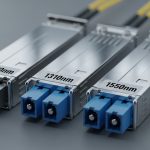
| Wavelength | Confirm SR/LR/ER class | 850 nm (SR), 1310 nm (LR), 1550 nm (ER/LR4) | Wrong wavelength yields near-zero receive power |
| Reach | Distance vs link budget | SR: 300 m OM3, 400 m OM4 (typical) | Overreach leads to high BER and intermittent link drops |
| Connector | LC vs SC | LC for most modern transceivers | Prevents physical mating and can introduce extra loss via adapters |
| Optical power | Tx/Rx ranges and sensitivity | Vendor datasheet values in dBm | Aruba ports may surface borderline links as early failures |
| DOM support | DOM presence and fields | Temperature, bias, Tx power, Rx power | Missing or nonconforming DOM can trigger alarms or port disable |
| Temperature range | Industrial vs commercial | 0 to 70 C or wider | Thermal drift can degrade optical output and raise errors |
Concrete examples of widely deployed optics
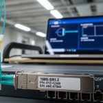
In the real world, admins often standardize on models with known DOM behavior. For 10G SR over multimode, you will commonly see vendor optics such as Cisco-compatible 10G SR parts from Finisar or others; examples include Finisar FTLX8571D3BCL for 10GBase-SR class optics. For Aruba deployments, operators also source third-party optics like FS.com SFP-10GSR-85 (10G SR) or Aruba-branded equivalents where available. Always validate the precise part number and DOM datasheet, because similarly named SKUs can differ in EEPROM layout or power class.

Step-by-step Aruba transceiver compatibility verification workflow
This is the implementation path I use when rolling optics across multiple closets. It reduces downtime by turning compatibility into a measurable checklist: configure the port, confirm the optics class, validate DOM and link health, then lock in the configuration. Follow these steps in order and you will catch most incompatibilities before they become outages.
Confirm port speed, interface type, and admin state
On Aruba switches, ensure the port is set to the correct speed and media type for the transceiver class. For example, if you are moving from 10G SFP+ to 25G SFP28, the port must support 25G and the transceiver must match. Also confirm the port is administratively up and not in a suspended state due to previous errors.
Expected outcome: Port shows the correct speed capability and is ready to train the link.
Validate transceiver class against the fiber plant
Match optics to the fiber type: SR at 850 nm for OM3/OM4 multimode, and LR at 1310 nm for single-mode OS2. Use your measured loss where possible, including patch panels, splices, and adapters. If you cannot measure, assume conservative margins and treat third-party “reach” claims as best-case.
Expected outcome: Link budget shows adequate optical margin for worst-case temperature and aging.
Insert the module and verify DOM visibility
After insertion, verify DOM parameters are readable by the switch or your telemetry collector. If Aruba Central or your monitoring stack shows DOM fields such as temperature and optical power, confirm they populate and remain within vendor-recommended ranges. If DOM is missing, check whether the transceiver is “DOM-capable” for that exact model and whether the switch expects specific SFF fields.
Expected outcome: DOM reads succeed and telemetry stops reporting invalid or absent fields.
Validate link health counters immediately
Bring up the link partner and watch for stability in the first minutes. Check interface error counters for CRC errors, symbol errors, and optical alarms. A link that “goes up” but accumulates errors quickly usually indicates marginal optical power or fiber polarity/connector issues.
Expected outcome: Errors remain at or near zero; no link flaps occur during a short stabilization window.
Lock in configuration and document the transceiver SKU
Once stable, record the exact SKU, vendor, wavelength class, reach rating, and any DOM observations in your change ticket. In mixed-vendor networks, documentation becomes the difference between a fast recovery and a long outage. For long-term reliability, standardize on a small set of validated part numbers per speed and reach class.
Expected outcome: Repeatable deployment with minimal unknown variables for future swaps.

Real-world Aruba transceiver compatibility scenario in a leaf-spine fabric
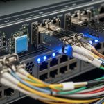
Consider a 3-tier data center leaf-spine topology with 48-port 10G ToR switches connecting to aggregation and spine layers. The site uses OM4 multimode for 300 to 380 m links across patched corridors, with LC trunks and short patch runs that add roughly 1.5 dB of connector and adapter loss per hop. An admin replaces failing optics during an RMA cycle, deploying third-party 10G SR transceivers in the ToR to aggregation links.
On the first day, the links appear up, but telemetry flags intermittent “DOM threshold” warnings. After investigation, the replacement SKU’s DOM fields map differently for vendor-specific thresholds, and the switch’s monitoring interprets them as out-of-range. The operational fix is not to change fiber, but to standardize on a transceiver model with validated DOM implementation and to align the monitoring thresholds to Aruba’s expected interpretation. After the change, link stability improves and the alarm volume drops, restoring operational calm.
Selection criteria and decision checklist for Aruba transceiver compatibility
Use this ordered list when selecting Aruba-compatible optics across multiple sites. It is designed to reduce both immediate failures and long-term reliability drift.
- Distance and link budget: verify reach against measured loss, not only datasheet claims.
- Switch compatibility: confirm the exact Aruba switch model and software version supports the optics class without restrictive checks.
- Data rate and electrical class: ensure the transceiver matches port speed (SFP+ vs SFP28 vs QSFP28).
- Wavelength and fiber type: SR 850 nm for OM3/OM4, LR 1310 nm for OS2, and avoid “it is probably fine” assumptions.
- DOM support and monitoring expectations: verify DOM capability and field semantics; confirm no invalid DOM warnings.
- Operating temperature range: match ambient conditions; consider derating for hot aisles.
- Vendor lock-in risk: balance OEM optics price against third-party reliability and your ability to standardize SKUs.
Common pitfalls and troubleshooting tips for compatibility failures
Even with careful planning, a few failure modes repeat like refrains. The best response is fast diagnosis with a disciplined sequence: verify optics class, confirm DOM and optical power, then inspect the physical layer. Below are the top pitfalls I see in production.
Pitfall 1: Link never comes up after insertion
Root cause: wavelength or fiber type mismatch (for example, inserting an 850 nm SR module into a single-mode path, or using the wrong transceiver class for the fiber plant). Another cause is a port speed mismatch where the switch expects a different optics class.
Solution: confirm transceiver wavelength and fiber type, then check port speed configuration. Measure receive optical power if your platform exposes it via DOM; if Rx power is near the noise floor, suspect mismatch immediately.
Pitfall 2: Link flaps under load while errors climb
Root cause: marginal optical budget due to excessive patching loss, worn connectors, or over-distance use beyond the rated reach. Third-party optics with slightly different launch power or receiver sensitivity can tip a borderline design into failure.
Solution: re-check the link budget with conservative margins, inspect and clean connectors, and replace with a higher-power or longer-reach validated SKU. If possible, re-run BER-related counters after cleaning and retesting.
Pitfall 3: DOM alarms, telemetry gaps, or “invalid readings”
Root cause: nonconforming DOM implementation or EEPROM parsing differences between module vendors and the switch’s expectations. The link may still work, but monitoring can interpret values incorrectly.
Solution: verify DOM-capable SKU documentation, compare EEPROM layout claims in the vendor datasheet, and standardize to a validated transceiver part number. Adjust monitoring thresholds only after confirming the DOM values are meaningful and consistent.
Cost and ROI note: balancing OEM optics with third-party risk
Pricing varies by speed and reach, but in many enterprise deployments, OEM-compatible optics carry a premium of roughly 20% to 60% over third-party equivalents. Third-party modules can reduce capex, yet they add operational risk: more time spent on compatibility validation, higher likelihood of DOM quirks, and the need to standardize part numbers across sites. From a TCO perspective, the best ROI usually comes from choosing a small set of validated third-party SKUs and treating them as controlled inventory, not as ad-hoc swaps.
In practice, a single optics-related outage can erase months of savings through downtime and troubleshooting labor. If your team can automate DOM validation and link health checks, third-party optics often pencil out well; if you cannot, OEM optics may be cheaper in the long run when you include operational time and risk management.
FAQ: Aruba transceiver compatibility questions admins actually ask
Which Aruba switch models are most sensitive to transceiver DOM behavior?
Sensitivity varies by platform generation and software release. If your monitoring shows DOM parsing errors, start with the exact switch model and compare behavior across a known-good Aruba-branded optics SKU versus the replacement third-party SKU.
Can I use third-party SFP+ or QSFP28 modules on Aruba ports?
Often yes, provided the module matches the electrical class, wavelength, reach, and DOM expectations. The safest approach is to validate one module per speed and reach class in a controlled window, then standardize the SKU if it behaves consistently.
What should I check first when a link stays down?
Confirm port speed configuration and optics class, then verify wavelength against fiber type. Next, check DOM and optical receive power; near-zero Rx power strongly indicates mismatch or a physical layer issue such as polarity or connector contamination.
Why does the link come up but alarms appear immediately?
That pattern commonly points to DOM field interpretation differences or threshold mismatches. Verify whether the transceiver is truly DOM-capable for that exact model and compare telemetry values with a known-good module.
How do I prevent compatibility regressions during future swaps?
Maintain an approved transceiver catalog per port speed and reach class, including exact part numbers and validation notes. Store evidence from your initial tests: DOM read success, link stability duration, and error counter baselines.
Is it better to standardize on OEM optics or a vetted third-party set?
OEM optics minimize surprises, but can cost more upfront. A vetted third-party set can provide strong ROI if you control SKUs, validate DOM behavior, and track operational outcomes across sites.
If you want the next layer of assurance, review your fiber plant and connector hygiene plan, because optics cannot outvote dust. Start with fiber cleaning and connector hygiene for high-speed links to reduce silent loss that masquerades as compatibility.
Author bio: I design and operate resilient enterprise networking systems, with hands-on experience validating optics, DOM telemetry, and failover behavior in production fabrics. My work focuses on measurable uptime, repeatable change control, and pragmatic recovery plans for real-world outages.