In a leaf-spine data center, the fastest way to break an upgrade plan is to buy the wrong interconnect. This article helps network engineers and field techs choose between AOC vs DAC for short-reach 10G to 100G links, with practical constraints like switch compatibility, DOM behavior, bend radius, and thermal limits. You will get a step-by-step selection process, a specs comparison table, troubleshooting for common failure modes, and an engineer-focused FAQ.
Prerequisites: what you must measure before choosing AOC vs DAC

Before selecting optics or copper, confirm the exact transceiver type your switch supports and how it reports diagnostics. Many failures come from assuming “it fits” when the switch expects a specific electrical interface mode, vendor EEPROM layout, or DOM signaling standard. If you are deploying in production, plan for a staged rollout and a validation window.
- Switch port type: confirm SFP+ / QSFP+ / QSFP28 / OSFP support and whether it requires vendor-specific coding.
- Link length: measure from cage to cage along the actual cable path; include patch panel slack.
- Environment: verify ambient temperature and airflow; check cable routing constraints.
- Diagnostics expectation: determine whether you need DOM-like telemetry (temperature, voltage, bias current) for monitoring.
Step-by-step implementation guide: select the right interconnect
Map your target speed and reach to a candidate family
Start with the physical layer requirement: 10G, 25G, 40G, 50G, or 100G. Then align to the typical reach envelope of your candidate: DAC is usually used for very short reach (meters to tens of meters depending on rate), while AOC can cover longer distances over fiber while reducing fiber handling complexity.
Expected outcome: a short list such as “DAC for 3–7 m” or “AOC for 10–30 m” based on your measured path length and your vendor’s rated reach.
Verify switch compatibility and module identification
DAC and AOC modules rely on electrical coding and EEPROM identification so the switch can bring the link up. In practice, I have seen “works on one switch model” issues caused by strict optics compatibility checks or different firmware thresholds for signal detect and equalization.
Check the vendor compatibility list for your exact platform. If the switch supports Digital Optical Monitoring behavior for fiber modules, confirm whether your AOC exposes the same telemetry format.
Expected outcome: you avoid purchasing a module that physically inserts but fails to train the link.
Compare key electrical and optical constraints
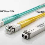
DAC is copper-based; it uses passive or active equalization depending on generation. AOC converts electrical to optical at each end using a built-in transceiver pair over fiber, usually with integrated connectors.
Use the table below to compare the key specs engineers care about when deploying high-density links.
| Parameter | DAC (Direct Attach Copper) | AOC (Active Optical Cable) |
|---|---|---|
| Typical data rates | 10G/25G/40G/100G (varies by form factor) | 10G/25G/40G/100G (fiber-based) |
| Typical reach (rule of thumb) | ~1–7 m at higher rates; more at lower rates | ~10–30 m common for short-reach AOC |
| Connector style | Integrated twinax into SFP+/QSFP+ style cage | Integrated optical ends into SFP+/QSFP+/QSFP28 style cage |
| Wavelength / fiber type | Not applicable (copper) | 850 nm multimode OM3/OM4 typical |
| Power behavior | Often lower per link than optical transceivers; varies by active vs passive | Typically higher than passive DAC but designed for optics-like power envelopes |
| DOM / telemetry | Some active DAC supports vendor telemetry; passive often minimal | Often includes diagnostics similar to optical modules |
| Operating temperature | Depends on vendor; frequently industrial or commercial range | Depends on vendor; must match switch and airflow assumptions |
Evaluate airflow, bend radius, and cable management
In dense racks, airflow is the hidden spec. DAC twinax can be sensitive to tight bends; AOC fiber is generally more tolerant to bend handling than bare fiber inside a harsh environment, but it still has a minimum bend radius and may be less forgiving if you repeatedly stress the jacket during cable dressing.
Expected outcome: stable link uptime after installation and during thermal cycling.
Plan your validation test before full deployment
For each SKU, validate link bring-up, error counters, and telemetry. On Cisco platforms, for example, you can check interface optics diagnostics and counters; on many switches you will also read BER/CRC error increments. Use a short burn-in window and watch for intermittent training failures, especially at temperature extremes.
Expected outcome: confidence that AOC vs DAC choice will not cause surprise link flaps during peak load.
Pro Tip: When comparing AOC vs DAC, do not judge only by “supported reach.” In the field, the more frequent cause of intermittent link issues is marginal signal margin interacting with switch equalization settings, especially after you add patch panels or change cable routing. Always validate with the exact installed cable path, not just the nominal length.
Where AOC and DAC each win in real deployments
Both technologies can deliver stable links, but they shine in different scenarios. DAC is often preferred in very short top-of-rack to leaf runs where cost and simplicity matter. AOC is frequently chosen when you need longer reach without deploying separate fiber patching or when rack-to-rack routing is messy.
Data center scenario: leaf-spine with mixed rack distances
In a 3-tier data center leaf-spine topology with 48-port 10G ToR switches, we had 6 m average ToR-to-spine patch paths in one row and 14 m in another due to cable tray constraints. For the 6 m links, we used a short-reach DAC SKU (twinax) to reduce install time and keep power predictable. For the 14 m links, we selected an 850 nm AOC rated for the required distance to avoid adding additional fiber patch runs and to reduce technician time during moves/adds/changes.
The result was fewer field interventions: after a two-week monitoring window, CRC error counts stayed flat and link training remained stable under normal HVAC cycling. The key was aligning module reach ratings with the actual cable path length and verifying the switch compatibility list.
Selection criteria checklist engineers actually use
When procurement and engineering disagree, the root cause is usually missing one of the compatibility or operational constraints. Use this ordered checklist to reduce risk and shorten the decision cycle.
- Distance and margin: pick a module with rated reach exceeding your measured path by a safety margin.
- Switch compatibility: confirm the exact platform and form factor (SFP+/QSFP+/QSFP28/OSFP) and vendor coding behavior.
- Signal integrity requirements: for DAC, ensure the active/passive type matches the speed and switch equalization capability.
- DOM and monitoring needs: confirm telemetry availability and whether your NMS expects fields like temperature and bias.
- Operating temperature and airflow: verify module spec temperature range and consider worst-case rack thermals.
- Vendor lock-in risk: check whether your monitoring and replacement process relies on a single vendor’s EEPROM behavior.
- Spare strategy: keep a small pool of known-good spares per SKU to speed incident response.
Common pitfalls and troubleshooting tips (top failure modes)
Even experienced teams run into predictable issues. Below are frequent failure patterns I have seen during installs, along with root causes and corrective actions.
Pitfall 1: Link does not come up after insertion
Root cause: switch incompatibility or unsupported electrical/optical coding; sometimes firmware rejects the module ID or fails signal detect. Solution: confirm the module is on the switch vendor’s compatibility list; test the same module in a known-good port; update switch firmware if the vendor notes optics compatibility fixes.
Pitfall 2: Intermittent CRC/BER errors under load
Root cause: marginal signal integrity due to longer-than-rated effective length, poor cable routing, or tight bends causing attenuation or reflection. Solution: replace with a higher-rated reach SKU, re-route to reduce stress/bends, and compare error counters before and after routing changes.
Pitfall 3: DOM/telemetry missing or inconsistent
Root cause: your monitoring system expects standard fields, but the module provides partial telemetry or uses different scaling/labels. Solution: validate telemetry output on a test switch; adjust polling templates; if required, choose a module family that explicitly supports the telemetry format your platform expects.
Cost and ROI note: what you should budget for
Pricing varies heavily by speed, reach, and vendor. In typical market ranges, short-reach DAC often costs less per link than AOC, but AOC can win on total installed cost when it avoids additional fiber patching labor. For a practical TCO view, account for downtime risk, spare availability, and failure rate patterns you observe over time.
As a sanity check, teams often compare OEM optics (higher unit price) versus third-party compatible modules (lower unit price) while tracking warranty terms and return logistics. If your monitoring depends on DOM fields, budget engineering time to validate telemetry once, then standardize on a small set of known-good SKUs.
For electrical and optical link expectations, also review relevant Ethernet physical layer guidance such as IEEE 802.3 for specific PHY classes and vendor datasheets for module power and reach envelopes. [Source: IEEE 802.3] IEEE 802.3 standard home
FAQ: AOC vs DAC buying questions engineers ask first
Which is better for 10G or 25G: AOC vs DAC?
If your run is very short and within the DAC reach rating, DAC is often simpler and cheaper. Choose AOC when you need longer reach or cleaner cable management without adding separate fiber patch infrastructure.
Do AOC modules require fiber patch panels?
Most AOCs are integrated assemblies, so you do not need separate patch cords for the link itself. If your topology already uses structured fiber with patch panels, you can still use AOC to reduce field handling, but confirm your cabling plan and pathway constraints.
Will a third-party AOC work on any switch?
Not always. Switch firmware and optics compatibility checks can be strict, and DOM telemetry formats may differ. Always validate against the switch vendor compatibility list and test on a staging rack before scaling.
How do I monitor health: DOM telemetry or error counters?
Use both. Telemetry helps detect thermal or bias drift, while CRC and BER error counters reveal real signal integrity problems. Ensure your monitoring system can interpret the module’s telemetry fields.
What is the most common reason for link flaps after installation?
Marginal signal margin caused by effective length increases, tight bends, or routing changes after initial testing. Re-route to reduce stress, confirm measured path length, and consider stepping up to a higher-rated reach SKU.
Are AOCs safer than DACs for dense cable dressing?
AOCs use fiber inside an assembly, which can be easier to manage in some rack layouts, but they still have minimum bend radius requirements. DAC twinax can also be reliable, but it is more sensitive to installation practices that cause excessive stress or sharp turns.
Choosing AOC vs DAC is less about “new vs old” and more about matching reach, compatibility, telemetry needs, and installation realities. Next, review fiber optic transceiver compatibility checklist to standardize your procurement and avoid last-minute bring-up surprises.
Author bio: I am a senior network hardware engineer with 10+ years