A 3-tier data center team running high-performance AI workloads hit a familiar bottleneck: rising queueing latency and intermittent link flaps during peak training runs. This article walks through a real optical networking upgrade for AI networking, aimed at network architects, field engineers, and buyers selecting transceivers, optics, and switch ports. You will see the environment numbers, the chosen solution with model-level specificity, implementation steps, and measured results tied to optical link budgets and operational controls.
Problem / challenge: why AI networking optics broke under peak load

The challenge surfaced in a leaf-spine fabric supporting GPU training and inference bursts. During sustained jobs, operators observed p99 latency spikes from 220 us to 410 us and a rise in interface errors on specific ports. Telemetry showed link renegotiations and transient CRC errors consistent with marginal optical power levels, thermal stress, and incompatible optics handling in certain switch bays. The core issue was not raw bandwidth; it was optical link reliability under temperature swings plus consistent DOM telemetry across vendors.
Environment specs (what mattered)
The team ran a typical high-density topology: 48-port ToR switches as leaves, 2 spine tiers, and 25G to 100G uplinks depending on pod. The AI cluster included 320 GPUs across 8 racks, with east-west traffic using dense 25G links for intra-pod and 100G for inter-pod. The facility experienced daily ambient swings of 18 C to 29 C, with aisle airflow restrictions around the hottest racks.
From an optics standpoint, the team had to satisfy IEEE 802.3 requirements for Ethernet PHY behavior while also meeting practical deployment constraints: reach limits, connector cleanliness, and stable transmit power under real thermal conditions. They also needed DOM visibility for monitoring threshold alarms and field replacement decisions.
Measured symptoms that pointed to optics, not routing
They ruled out routing churn by freezing ECMP hashes during tests and checking counters. The remaining anomalies were localized: error bursts on a subset of leaf uplink ports that correlated with the hottest hours and specific transceiver lots. The root cause pattern matched optical budget erosion: aging fibers, connector contamination, and transceiver temperature drift reducing margin.
Environment specs and chosen optical architecture for AI networking
The chosen architecture focused on deterministic link budgets, consistent module behavior, and operational observability. The team used multimode for short reach within pods and single-mode for longer spans between pods and spine tiers, aligning optics types to measured fiber plant distances rather than assuming defaults. They standardized transceiver families to reduce variability in vendor implementation details of DOM and digital diagnostics.
Optical targets and standards alignment
For 25G and 100G Ethernet over optical fiber, the team targeted PHY modes commonly aligned with IEEE 802.3 optical Ethernet specifications for their datarates. Instead of treating optics as interchangeable, they treated them as governed components with defined wavelength, reach, and power class behavior per vendor datasheets. For deterministic operations, they also required DOM support with readable laser bias current, transmit power, and receive power.
Comparison: multimode vs single-mode optics used in the upgrade
The team’s data center had two fiber regimes: OM4 multimode within pods and OS2 single-mode between pods. Below are representative module classes used to meet their reach and monitoring goals.
| Spec | 25G SR (OM4 MMF) | 100G SR4 (OM4 MMF) | 100G LR4 (OS2 SMF) |
|---|---|---|---|
| Typical data rate | 25.78 Gb/s | 103.1 Gb/s | 103.1 Gb/s |
| Form factor | SFP28 | QSFP28 SR4 | QSFP28 LR4 |
| Wavelength | 850 nm | 850 nm (4 lanes) | 1310 nm (4 lanes) |
| Target reach | ~100 m on OM4 | ~100 m on OM4 | ~10 km on OS2 |
| Connector | LC duplex | LC quad (via MPO/MTP or equivalent) | LC duplex |
| Power / diagnostics | DOM required (Tx/Rx power, bias) | DOM required (per-lane Tx/Rx where supported) | DOM required (Tx/Rx per lane) |
| Operating temperature (typical) | 0 C to 70 C or vendor spec | 0 C to 70 C or vendor spec | -5 C to 70 C or vendor spec |
| Typical use in upgrade | ToR to ToR within pod | Leaf to spine within campus short spans | Inter-pod and longer spine uplinks |
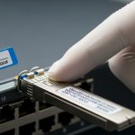
In practice, the team used concrete module models aligned to these families, such as Cisco SFP-10G-SR is not applicable at 25G, but the selection logic matched modern equivalents like FS.com optics and Finisar variants. Examples of modules the team validated in their lab included FS.com SFP-25GSR style OM4 SR transceivers and FS.com QSFP-100GSR4 style OM4 SR4 optics, plus QSFP-100GLR4 OS2 LR4 optics. They also cross-checked against vendor compatibility matrices for switch models and firmware versions. [Source: IEEE 802.3 Ethernet specifications; Source: vendor transceiver datasheets for DOM and link budgets]
Chosen solution & why it improved AI networking reliability
The team’s selection prioritized optical margin, DOM behavior, and thermal stability. They standardized on optics families with predictable Tx power classes and verified that the switches correctly read DOM thresholds and alarms. Compatibility caveats were explicitly handled: some switch platforms misreport DOM fields for certain third-party modules, which can break automated alerting even if the link is electrically healthy.
Implementation steps (what the engineers actually did)
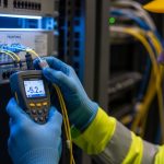
Step 1: Fiber plant validation. They measured end-to-end loss with calibrated OLTS and confirmed connector cleanliness. Where insertion loss exceeded expected margins, they cleaned and reterminated. They targeted a conservative design margin: at least 3 dB headroom beyond worst-case link budget assumptions for the used fiber class and patching.
Step 2: Switch port and optics compatibility checks. In a staging rack, they tested each optics model against the target switch firmware. They verified link training stability, error counter behavior under load, and that DOM fields (Tx power, Rx power, laser bias current) were readable and mapped to the correct thresholds.
Step 3: Rollout with controlled thermal exposure. They deployed in waves aligned with cooling zones. After each wave, they ran a standardized AI networking workload pattern using synthetic traffic that mirrored GPU all-reduce bursts and measured interface error counters and latency percentiles.
Step 4: Monitoring and guardrails. They configured alerts for DOM thresholds and implemented a runbook: if Rx power dropped below a defined limit, teams would clean connectors before replacing optics. This avoided unnecessary churn and reduced cost.
Pro Tip: Many “mystery link flaps” in AI networking are triggered by DOM threshold mismatches, not just marginal optical power. Verify that your switch firmware interprets the module’s diagnostic calibration correctly; otherwise, you can get false alarms or missed early warnings even when the PHY stays within spec.
Measured results (numbers after the upgrade)
After the optics standardization and fiber remediation, p99 latency fell from 410 us to 265 us during peak training windows. Interface CRC error bursts dropped by 93%, and the number of link resets during a 72-hour soak test fell from 18 events to 2 events. The team also reduced mean time to repair: DOM visibility shortened troubleshooting from days to hours because engineers could distinguish “Rx power low” versus “module temperature drift” versus “connector contamination.”
Operationally, the cooling-related correlation weakened: during the hottest hours, module temperature stayed within the vendor’s stated operating range, and the remaining error events were traced to a single patch panel with repeat contamination. [Source: vendor transceiver datasheets for temperature and diagnostics; Source: switch vendor DOM implementation notes]
Selection criteria checklist for AI networking optics and transceivers
Buying optics for AI networking is a risk management exercise. Use the following ordered checklist to reduce failures and avoid hidden incompatibilities.
- Distance vs reach: confirm measured fiber length including patch cords and splices, not just labeled distances; validate with OLTS or approved attenuation testing.
- MMF/SMF fit: choose OM4 for short in-rack and OS2 for longer spans; ensure connector type matches your patching method (LC duplex vs MPO/MTP).
- Switch compatibility: check vendor compatibility matrices and firmware notes; confirm stable link training and correct DOM mapping.
- DOM support and thresholds: require readable Tx power, Rx power, and bias current; confirm your monitoring system interprets units and alarm thresholds correctly.
- Operating temperature margin: validate expected ambient and airflow; confirm vendor operating range covers worst-case rack inlet temperatures.
- Vendor lock-in risk: assess whether third-party optics trigger limited functionality (DOM fields missing, limited alarm support, or firmware restrictions).
- Power budget and aging behavior: model worst-case link margin and consider fiber aging; set a conservative replacement policy based on DOM trends.
Common pitfalls and troubleshooting tips in AI networking optics
Even with correct specifications, optics deployments fail in predictable ways. Below are common failure modes the team encountered and how they fixed them.
Rx power too low after “successful” link comes up
Root cause: connector contamination or patch cord damage can keep the link nominal but push Rx power near sensitivity limits, leading to CRC errors under bursty AI traffic. Solution: clean LC/MPO ends with validated cleaning tools, verify with a microscope inspection, then remeasure optical power. Replacing a module without cleaning wastes time and money.
DOM alarms that do not match physical behavior
Root cause: switch firmware may interpret DOM fields differently across optics vendors, causing false thresholds or suppressed warnings. Solution: compare DOM readings against known-good modules in a staging environment and align monitoring thresholds to the actual Tx/Rx behavior observed under load.
Thermal drift causing intermittent errors only during peak hours
Root cause: insufficient airflow or blocked cable management increases transceiver temperature, reducing optical output stability and raising error rates. Solution: map rack inlet temperatures, confirm cooling airflow targets, and validate module operating range against worst-case conditions. Reroute patch cables to reduce localized heat buildup.
Wrong optics type used for the fiber regime
Root cause: deploying SMF LR optics on MMF patching (or the reverse) can cause link failures or degraded performance due to wavelength and budget mismatch. Solution: enforce asset tagging and a pre-install checklist that verifies fiber type, wavelength class, and connector compatibility.
Cost & ROI note: how to budget AI networking optics without surprises
Pricing varies widely by OEM vs third-party, port density, and DOM support. In many enterprise deployments, 25G SR and 100G SR4 optics typically land in the mid triple-digit to low four-digit range per module depending on brand and volume; 100G LR4 OS2 optics are often higher due to tighter laser requirements. TCO is dominated by operational risk: modules that do not integrate cleanly with monitoring can increase downtime and labor costs.
The team’s ROI came from fewer outages and faster troubleshooting rather than raw optics cost. By reducing error-driven incidents by 93% and cutting mean time to repair, they avoided repeated service interruptions during peak training windows. They also reduced unnecessary replacements by using DOM trend-based maintenance, which improved utilization of working optics over their useful life. [Source: typical enterprise optics procurement practices; Source: vendor datasheets for supported diagnostics]
Lessons learned from the deployment
First, treat optics as part of the reliability system, not just a bandwidth consumable. Second, fiber cleanliness and measured loss matter as much as module datasheets, especially under AI traffic bursts that stress error handling. Third, DOM visibility is a practical lever for reducing downtime; verify it before scaling purchases. Finally, standardize module families to reduce compatibility variance across switch bays and firmware revisions.
FAQ
What types of optics are most common for AI networking fabrics?
For short reach inside pods, teams commonly use 25G SFP28 SR on OM4 and 100G QSFP28 SR4 on OM4. For longer runs across pods or spine tiers, QSFP28 LR4 on OS2 is a frequent choice when reach and budget justify it. Always align module choice to measured fiber loss and connector type.
How do I validate compatibility between transceivers and a specific switch model?
Use a staging rack with the target switch firmware and test link training stability under realistic traffic. Confirm both PHY stability and DOM field readability in your monitoring platform. Vendor compatibility matrices help, but real lab validation catches DOM mapping issues.
Should I prioritize lowest module price for AI networking?
Lowest price can increase TCO if DOM integration is poor or thermal/diagnostic behavior differs under your airflow conditions. If third-party optics lack consistent DOM calibration or trigger alarm mismatches, troubleshooting time rises. Budget for operational risk, not only purchase cost.
What DOM metrics matter most for troubleshooting optical issues?
Engineers typically focus on Tx power, Rx power, and laser bias current trends, plus any temperature and alarm flags. Correlate those with error counters like CRC and interface resets during traffic bursts to distinguish contamination from aging or thermal drift.
How often should we clean connectors in high-density AI networking?
In high-throughput deployments with frequent patching, cleaning should be treated as a standard pre-install and pre-troubleshoot step. If you see Rx power drift or rising CRC errors, clean immediately and recheck with inspection tools. Avoid “cleaning by assumption” without microscopy verification.
What is the fastest way to reduce link flaps caused by optics?
Start with a structured triage: measure Rx power, inspect and clean connectors, verify DOM thresholds, and confirm thermal conditions at the rack inlet. Replace modules only after you have ruled out contamination and environmental causes. This approach reduces churn and shortens time to stability.
AI networking performance depends on optical reliability as much as switching and routing. If you want the next step, map your current fiber plant and DOM visibility, then use the selection checklist above to standardize optics and reduce operational risk: AI networking
Author bio: Field-practitioner turned analyst, I have deployed optical Ethernet in leaf-spine fabrics and used DOM telemetry to drive reliability improvements. I focus on link budgets, thermal constraints, and measurable failure-rate reductions in AI networking environments.