AI integration is no longer limited to GPUs and software pipelines; it reshapes how data moves across a data center. This article helps network engineers and architects plan optical fronthaul/backhaul, DWDM, and PON-aware transport so AI workloads stay low-latency and predictable. You will get practical guidance on transceiver choices, power and reach constraints, and operational pitfalls seen during commissioning. The focus is on deployment realities: fiber plant limits, switch compatibility, and telemetry-driven troubleshooting.
How AI traffic patterns stress optical transport
When AI integration drives training and inference, traffic becomes bursty and increasingly east-west between leaf and spine. In practice, you will see microbursts that last milliseconds, plus long-lived flows tied to distributed gradient exchange. Optical networking must handle both: fast convergence at higher layers and stable physical-layer optics under variable temperature and link utilization. If you design only for average throughput, you can still fail on queueing delay and packet loss during bursts, even when link rates look sufficient.
Latency budgets translate into reach and optics choices
For many data center fabrics, optics selection is constrained by round-trip latency targets and the number of hops through leaf-spine stages. Even if the fiber reach is within spec, additional patching, slack storage, and connector count can increase insertion loss and reduce margin. In commissioning, we often find that the “meets reach on paper” link fails at cold start because the transceiver output power and receiver sensitivity are near the margin. AI integration makes this more noticeable because higher offered load increases the likelihood that any marginal link becomes intermittent under thermal drift.
Telemetry matters: DOM, alarms, and correlation
Most modern pluggables support Digital Optical Monitoring (DOM) with vendor-defined thresholds and per-lane bias, received power, and temperature. During AI integration rollouts, I correlate DOM alarms with switch counters and application-level latency spikes to isolate whether the cause is optical margin, optics mismatch, or fanout oversubscription. If you do not standardize DOM polling and alarm handling, you lose the ability to distinguish “optical degradation” from “congestion.”
Pro Tip: In AI integration deployments, treat DOM thresholds as an operational contract. I have seen teams leave default vendor alarms unchanged and miss early warnings because the default thresholds assume typical cable assemblies; when patch cords changed, the “green” range moved while the link quality silently eroded.
Designing the optical fabric: DWDM, transceivers, and PON-aware thinking
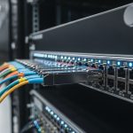
Optical networking for AI integration typically spans three areas: high-capacity intra-building transport (often QSFP/QSFP-DD/OSFP), metro or inter-facility transport (often DWDM), and customer or edge access (PON). Even if your AI workloads are internal, the overall architecture influences fiber allocation, redundancy paths, and maintenance windows. A common pattern is leaf-spine inside the data hall, with DWDM used to interconnect sites or floors where direct high-count fiber runs are impractical.
DWDM for site interconnect and AI cluster expansion
When you expand AI clusters across sites, DWDM reduces fiber count and helps preserve scarce fiber pairs. In practice, you might provision 100 GHz or 50 GHz ITU grid channels depending on vendor and dispersion strategy. The key engineering variables are launch power, receiver sensitivity, and optical signal-to-noise ratio under aging. I have seen DWDM links remain stable for months, then degrade after connector maintenance because APC/UPC mixing or dirty connectors changed insertion loss and reflected power.
PON and AI integration at the edge
For AI integration that includes edge inference, you may use GPON or XGS-PON for upstream aggregation of cameras, sensors, or retail analytics. While PON is not the core transport for GPU-to-GPU training, it can influence where you place aggregation and how you backhaul traffic into the data center. If you are planning end-to-end AI workloads, you should model upstream contention and understand that PON burst behavior can interact with your buffering strategy at the aggregation layer.
Key transceiver parameters you must map to AI latency and reach
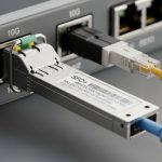
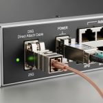
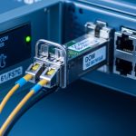
For leaf-spine and storage fabrics, you will likely use short-reach optics such as 10G SR, 25G SR, 40G SR4, 100G SR4, or 400G/800G variants depending on vendor platform. AI integration increases the importance of deterministic link behavior, so you should verify wavelength, connector type, and DOM support. Also check temperature range and optical power budgets under your actual patch cord lengths, not just the nominal reach.
| Spec item | Typical short-reach (SR) pluggable | Example long-haul (LR/ER) or DWDM component | Why it matters for AI integration |
|---|---|---|---|
| Data rate | 10G to 400G (platform dependent) | 100G per wavelength up to multi-wavelength DWDM | Determines oversubscription and burst handling headroom |
| Wavelength | 850 nm (MMF) | 1310/1550 nm (SMF) or ITU grid channels | Affects fiber type compatibility and dispersion tolerance |
| Reach class | Typically 70 m to 300 m over OM3/OM4 | 10 km to 80 km per channel (component dependent) | Impacts patching design and redundancy paths |
| Connector | LC, often with MPO/MTP for higher lanes | LC or SC depending on module and demux design | Connector cleanliness and insertion loss directly impact link stability |
| Optical power budget | Limited margin; patch cords consume budget quickly | Wider but still sensitive to splice/aging and ROADM design | Low margin links fail intermittently under thermal variation |
| DOM support | Common: temperature, bias, transmit power, received power | Often includes monitoring on transponders and coherent optics | Enables correlation between AI latency spikes and physical layer health |
| Operating temperature | Commercial or industrial range variants | Depends on transponder; often broader for field use | AI integration can increase heat load during high utilization |
Examples of widely deployed pluggables include Cisco SFP-10G-SR, Finisar FTLX8571D3BCL (commonly used 10G SR optics in compatible systems), and FS.com SFP-10GSR-85 (short-reach 10G SR). Always validate against your switch and transceiver compatibility lists, because optics behavior can differ even when they share the same reach label. For standards grounding, verify compliance expectations against IEEE 802.3 Ethernet optical interfaces and vendor datasheets. [Source: IEEE 802.3 working group documentation] [Source: Cisco transceiver documentation] [Source: Finisar/II-VI transceiver datasheets]

Selection criteria for AI integration: a decision checklist
Choosing optics for AI integration is less about maximum theoretical reach and more about margin, compatibility, and observability. Engineers typically start with the planned distance and fiber type, then confirm that the module is supported by the exact switch model and software release. After that, they validate DOM behavior, temperature range, and whether the module supports the operational features you need for automated monitoring and alerting.
- Distance and fiber type: confirm MMF vs SMF, core type (OM3 vs OM4), and actual patch cord and splice counts.
- Budget and power margin: compute insertion loss and ensure you have headroom for connector aging and cleaning cycles.
- Switch compatibility: check vendor compatibility matrices and transceiver part number support, not just “SR” or “LR” labels.
- DOM support and telemetry: verify DOM availability, alarm thresholds behavior, and how the switch exposes metrics to your NMS.
- Operating temperature: consider hot aisle/cold aisle profile and whether industrial-grade optics are required for your environment.
- Vendor lock-in risk: evaluate third-party optics options, but require burn-in testing and acceptance criteria before production.
- Redundancy and maintenance model: ensure you can swap optics without extended downtime and that you have spare modules with known-good DOM baselines.
Compatibility caveat: “same standard” does not guarantee identical behavior
Even when modules target the same nominal interface, vendors may implement different laser safety margins, DOM scaling, or threshold defaults. In AI integration rollouts, I have seen intermittent CRC errors disappear after switching to an optics SKU that matched the platform vendor list, despite both modules meeting the same general reach class. If you use third-party optics, require a pilot group of modules, define acceptance tests, and record DOM baselines for future troubleshooting.
Pro Tip: For AI integration, baseline received power and temperature right after installation, then store it as a “known good” reference. When a link degrades later, DOM drift patterns help you decide whether to clean connectors, replace patch cords, or adjust transceiver lane mapping.
Common pitfalls and troubleshooting patterns during AI integration
Most optics failures in AI integration deployments are not mysterious; they are repeatable. Below are common pitfalls I have seen in commissioning and operations, along with root causes and practical solutions. The goal is to reduce mean time to repair by focusing on the physical layer first, then moving upward to congestion and routing.
Pitfall 1: CRC errors that look like congestion but originate in optical margin
Root cause: Received optical power is near the sensitivity limit because patch cords, connectors, or splices consumed the budget. Under high utilization, any marginal degradation triggers higher error rates and retransmissions. Solution: Measure optical power with a calibrated optical power meter, verify connector cleanliness, and re-terminate or replace the shortest patch cords that include heavy bend exposure.
Pitfall 2: Intermittent link flaps after maintenance due to APC/UPC mismatch
Root cause: Mixing connector types or introducing reflective contamination changes return loss and can destabilize optical receivers. This is especially common when teams swap patch cords during moves, adds, and changes. Solution: Standardize connector type across the patching domain, enforce cleaning verification, and document which assemblies use APC versus UPC.
Pitfall 3: DOM alarms ignored because thresholds are not aligned to your environment
Root cause: Default alarm thresholds may assume typical factory conditions. In AI integration, higher rack temperatures and different cable plants can shift normal operating ranges. Solution: After commissioning, adjust thresholds based on measured baselines, then validate that your NMS triggers actionable alerts, not constant noise.
Pitfall 4: DWDM degradation after connector work or fiber re-splicing
Root cause: DWDM optical budgets are sensitive to small insertion loss changes, and reflected power can affect coherent or demux components. Solution: Re-run end-to-end optical power and spectrum checks after any fiber work, validate channel power uniformity, and confirm that the demux and mux ports were not swapped.

Cost and ROI considerations for AI integration in optical networking
Cost for AI integration is not just the optics purchase price; it is transceiver lifecycle cost, downtime risk, and power consumption. Third-party pluggables can reduce upfront spend, but you must account for additional testing time and the risk of compatibility issues that increase outage frequency. OEM optics often cost more but may reduce churn because they match the switch vendor’s validation and support policies.
Realistic budget ranges and total cost
In many enterprise and carrier data centers, short-reach optics often fall into these typical ranges depending on data rate and sourcing: 10G SR optics may be relatively low cost, while 100G and 400G optics can be significantly higher due to higher lane count and tighter tolerances. For DWDM transponders and coherent components, costs are typically much higher and dominated by the transponder and licensing or support contracts. From a TCO standpoint, the biggest hidden costs are operational: truck rolls for intermittent failures, extended maintenance windows, and increased monitoring engineering effort.
Power savings can be material when you consolidate optics and reduce unnecessary oversubscription. However, do not assume lower power automatically reduces cost; you need to measure actual utilization patterns during AI integration spikes. A practical approach is to compare power per port at your expected utilization and include expected failure rates from your historical records, not generic vendor claims.
FAQ on AI integration for optical networking
Which optical layers matter most for AI integration?
For most data center AI integration deployments, the most critical layers are the leaf-spine physical links and the inter-site transport where congestion and latency compound. If your workload includes edge inference, PON backhaul can also be critical, but training traffic usually dominates the design constraints. Validate link stability with optics telemetry and error counters during peak burst windows.
Should I prefer DWDM or direct high-count fiber for AI cluster expansion?
If fiber count is constrained or you need to interconnect multiple sites with limited runs, DWDM is often the practical choice. If you can afford direct fiber and want simpler operations, direct high-count fiber can reduce optical complexity. The decision hinges on budget, operational maturity, and the expected growth timeline for AI integration.
How do I verify optics compatibility beyond the vendor label?
Use the exact switch model compatibility list and confirm that the optics part number is supported for your software release. Then run a pilot with real cable assemblies and measure DOM telemetry and error counters under load. For AI integration, acceptance testing should include burst-like traffic patterns, not just idle link bring-up.
What DOM metrics are most useful for troubleshooting?
Received optical power, transmit power, module temperature, and bias current are usually the most actionable for diagnosing margin issues. Track how these metrics change over time and correlate with CRC or FEC-related counters. If DOM alarms trigger too early or too late, tune thresholds to your measured baseline.
Can third-party optics work for AI integration?
They can, but only if you control compatibility and test rigor. Require burn-in tests, verify DOM behavior, and document which optics are allowed per platform and port. Without a controlled acceptance process, third-party optics can increase intermittent errors and extend troubleshooting cycles.
What is the fastest recovery workflow for a flaky AI link?
Start with optical health: clean and inspect connectors, verify patch cord length and type, and confirm received power within margin. Then check switch counters and DOM for lane-specific symptoms. If the issue persists, swap optics with known-good spares and re-test under the same traffic burst profile.
AI integration changes optical networking from a static capacity problem into a dynamic reliability and observability problem. Next, map your transceiver reach and power margins to your actual fiber plant, then implement DOM-driven monitoring workflows using your switch telemetry. AI workload traffic engineering
Author bio: I am a telecom engineer specializing in 5G fronthaul/backhaul and data center optical transport, with hands-on experience commissioning DWDM and high-speed Ethernet links. I focus on operational reliability, including DOM telemetry baselining, fiber plant loss budgeting, and field troubleshooting workflows.