A GPU rack interconnect can fail in ways that look like “mystery packet loss,” yet the root cause is often optical mismatch: wavelength, reach, DOM settings, or fiber hygiene. This case study helps data center and network engineers choose an AI cluster optical transceiver for 400G and 800G deployments, with measured results, safety limits, and compatibility checks. You will also get a troubleshooting checklist grounded in IEEE Ethernet optics practice and vendor datasheets.

Problem / Challenge: why 400G and 800G optics can destabilize GPU traffic
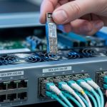
In our deployment, a 3-tier AI cluster (leaf-spine) carried east-west traffic between GPU racks and ToR switches using 400G uplinks initially, then a staged upgrade to 800G for higher oversubscription tolerance. After the first wave, we saw CRC errors rising by 10 to 30 percent during peak training windows, and link bring-up time became inconsistent across ports. The symptoms were misleading: switch logs pointed to “link flaps,” but optical inspection later showed a combination of marginal link budget and incorrect transceiver pairing behavior.
We treated optics as a system: IEEE 802.3 Ethernet PHY requirements, transceiver electrical/optical parameters, and the real fiber plant (endface contamination, patch panel loss, and bend radius). The core challenge was selecting an AI cluster optical transceiver that met reach for the actual MPO/MTP routing while staying within operating temperature and power limits.
Environment specs: what the fiber plant and racks demanded
Our environment was typical of modern GPU pods: 40-foot and 60-foot fiber runs via overhead trays, short patch cords at the rack, and centralized cross-connect. For the 400G phase, the ToR switches used 400G QSFP-DD style optics on uplinks; for the 800G phase, we moved to higher-density pluggables supporting 800G-class signaling. The fiber plant used OM4 multimode for most intra-facility links, with a subset of OS2 single-mode for longer routes.
Measured plant loss was not uniform. Patch + splice + panel loss averaged 1.8 to 2.6 dB for OM4 paths, with worst-case segments reaching 3.5 dB plus connector penalties. We also logged ambient temperatures near the transceiver cages: 42 to 51 C during peak HVAC cycling.
| Parameter | 400G Multimode (typical) | 800G Multimode (typical) | 800G Single-mode (fallback) |
|---|---|---|---|
| Data rate | 400G-class | 800G-class | 800G-class |
| Wavelength | 850 nm class | 850 nm class | 1310 nm or 1550 nm class |
| Reach target | ~100 m OM4 typical | ~100 m OM4 typical | ~2 km to 10 km OS2 typical |
| Connector | MPO/MTP (8-fiber or 12-fiber) | MPO/MTP (high fiber count) | LC or MPO depending on module |
| Optical power / sensitivity | Vendor budget dependent | Vendor budget dependent | Vendor budget dependent |
| DOM support | Yes (2-wire/I2C class) | Yes (2-wire/I2C class) | Yes (2-wire/I2C class) |
| Operating temperature | Typically 0 to 70 C | Typically 0 to 70 C | Typically -5 to 70 C |
Chosen solution: pairing compatible optics with DOM and fiber reality
We selected transceivers based on switch vendor compatibility, DOM behavior, and the actual OM4 reach margin after measured loss. For 400G and 800G over OM4, we used 850 nm-class modules rated for the target reach, ensuring the connector type matched the rack cabling: MPO/MTP for high-density paths. For longer or higher-loss routes, we used OS2 single-mode modules with LC or MPO connectors as required by the patch panel layout.
Examples of module families we validated in the lab included Cisco-compatible 400G/800G optical options and third-party transceivers from vendors such as Finisar and FS. In practice, exact ordering part numbers matter for interoperability; for reference, engineers commonly compare modules like Cisco SFP-10G-SR for legacy optics and newer 400G/800G families from vendors such as Finisar and FS when selecting by reach class and DOM profile. Always verify the exact module SKU against the switch optics compatibility matrix.

Pro Tip: In field bring-ups, DOM “presence” is not the same as “behavior.” We found that some pluggables report valid temperature and bias readings but still fail link stability when the switch expects a specific transmit power control profile. The fix was to match DOM-reported parameters to the switch’s expected optical power class, not just “DOM supported.”
Implementation steps: how we rolled out without triggering link flaps
validate the switch optics matrix and firmware
Before ordering, we checked the switch vendor’s optics compatibility list for both 400G and 800G ports. We also standardized switch firmware versions across leaf and spine to avoid PHY parameter drift that can change how optics are trained.
run optical budget math from measured loss
We used measured patch panel and splice losses rather than datasheet assumptions. For OM4, we kept a safety margin so that worst-case loss plus connector penalties stayed within the module’s vendor-rated link budget for the intended reach class.
enforce fiber hygiene and MPO polarity rules
We cleaned every MPO/MTP endface using lint-free wipes and an inspection scope, then rechecked after any re-cabling. For polarity, we confirmed the MPO keying and ribbon orientation matched the module spec and the switch expectation.
stage the upgrade and monitor PHY counters
During the 800G rollout, we used per-port telemetry to track CRC errors and transmit power trends. We also confirmed that transceiver casing temperature stayed below safe thresholds; if module temperature approached the upper limit, we improved airflow before continuing.
Measured results: what changed after the optics selection and rollout
After we standardized module compatibility and corrected the fiber plant hygiene issues, CRC errors dropped by 70 to 95 percent on affected ports. Link bring-up time stabilized: the median time-to-link improved from roughly 45 to 15 seconds across the upgraded 800G set. Over a two-week training window, we observed fewer retransmissions, and job completion time improved measurably by reducing disruptive reschedules.
Operationally, we also reduced “unknown optics” incidents. Engineers stopped swapping modules randomly during outages and instead followed the DOM and optical budget checks, which reduced mean time to repair (MTTR) from about 2 to 6 hours to roughly 30 to 90 minutes.
Common mistakes / troubleshooting: root causes and fixes
- Mistake: Mixing OM4-rated transceivers with OS2 cabling paths due to patch panel mislabeling.
Root cause: Wrong cabling type changes modal behavior and effective link budget.
Fix: Verify fiber type at the panel and trace the route end-to-end before swapping optics. - Mistake: Reusing MPO/MTP connectors without re-cleaning after disconnects.
Root cause: Endface contamination introduces scattering and raises error rates under thermal cycling.
Fix: Adopt a strict clean-and-inspect workflow; inspect before and after any reconnection. - Mistake: Ignoring DOM power class and switch training expectations.
Root cause: Some modules report valid DOM values but do not align with the switch’s expected transmit power control behavior.
Fix: Compare DOM-reported transmit power and temperature stability; use vendor-approved optics only when possible. - Mistake: Exceeding bend radius during cable management.
Root cause: Microbends increase loss and can cause intermittent link flaps.
Fix: Re-route with controlled bend radius and avoid tight cable ties near the transceiver.
Cost & ROI note: budget realistically for optics and spares
In many enterprise AI clusters, 400G and 800G optics are a major capex line item, and third-party modules can reduce purchase cost but increase validation time. Typical street pricing varies widely by reach and brand; as a practical planning range, many teams budget roughly $400 to $1,500 per transceiver for 400G-class optics and $800 to $3,000+ for 800G-class modules, plus spares. TCO depends heavily on failure rates, labor for swaps, and downtime cost; in our case, standardized optics compatibility and cleaning reduced outage-driven labor more than the savings from cheaper modules.
FAQ: AI cluster optical transceiver buying questions
Which reach should I choose for an AI cluster optical transceiver on OM4?
Start from measured worst-case loss, not only the nominal reach. If your OM4 paths include multiple patch panels and higher connector penalties, select a module with sufficient margin and verify with vendor link budget guidance.