In a live 5G network, the limiting factor is often not the radio, but the fiber links that carry fronthaul and backhaul traffic. Adaptive optical transceivers help operators maintain link margin under real-world aging, temperature swings, and connector contamination. This article helps network engineers and field technicians choose, validate, and troubleshoot adaptive optics using practical deployment criteria and measurable outcomes.
Why adaptive optics matter inside a 5G network
Most 5G transport runs over fiber, where optical power budgets and receiver sensitivity define whether a link stays error-free. Traditional “fixed” transceivers assume stable fiber conditions, but real deployments see gradual changes: splices age, dust migrates, and remote cabinets cycle temperature. Adaptive optical transceivers address this by dynamically adjusting transmitter parameters (for example, bias current and/or output power) and by using feedback mechanisms tied to the link’s optical performance. In practice, that means fewer marginal links that pass during commissioning but fail during seasonal peaks.
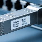
From an implementation standpoint, adaptive behavior is typically aligned with standardized interfaces such as IEEE 802.3 optical link definitions (for Ethernet over fiber) while the adaptation algorithm is vendor-specific. For 5G fronthaul, engineers often target low latency and deterministic transport, but the optical layer still must handle bursty traffic and tight link budgets. Vendors also expose operational telemetry through DOM (Digital Optical Monitoring) so you can correlate optical power, temperature, and error counters with network events.
When selecting adaptive modules for a 5G network, it helps to separate two goals: (1) maintaining optical margin and (2) reducing operational surprises. The first is about link stability; the second is about observability and consistent behavior during maintenance windows.

What “adaptive” means in real transceivers: parameters and telemetry
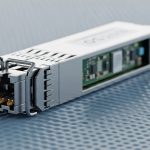
Adaptive optical transceivers commonly monitor received signal strength and adjust transmit characteristics to keep the link within a target operating window. Depending on the product family, adaptation may include output power control, laser bias management, and sometimes equalization behavior. The exact mechanism is not always fully documented in public datasheets, but field engineers can validate behavior through telemetry and link error statistics.
Key specs engineers check first
To evaluate whether an adaptive transceiver is appropriate for your 5G network, start with the optical and electrical envelope. Typical decision points include wavelength, reach class, receiver sensitivity, transmit power range, and connector type. For 5G transport, you also need operational temperature range because outside plant cabinets can exceed lab conditions.
Typical comparison: adaptive multimode and single-mode options
The table below shows representative characteristics you might see when comparing common 10G-class optics used in 5G transport designs. Exact values vary by vendor and revision, so treat these as engineering reference points and confirm against the specific datasheet for the module part number you plan to deploy.
| Parameter | 10G SR (Multimode) | 10G LR (Single-mode) | Example adaptive approach |
|---|---|---|---|
| Wavelength | ~850 nm | ~1310 nm | Variable output power based on link margin |
| Nominal reach class | Up to 300 m (OM3/OM4) | Up to 10 km (single-mode) | Maintains margin as fiber loss changes |
| Connector | LC | LC | Same form factor, adaptive control loop |
| Data rate / interface | 10G Ethernet (IEEE 802.3) | 10G Ethernet (IEEE 802.3) | Compatible with switch optics and DOM |
| Telemetry | DOM: Tx power, Rx power, temp | DOM: Tx power, Rx power, temp | Correlate adaptation with error counters |
| Operating temperature | Commercial or extended | Commercial or extended | Stability across temperature swings |
For 5G network deployments, the practical difference is how quickly the module recovers margin after a disturbance. For example, after a technician cleans an LC connection and reseats the module, an adaptive loop may shift output power to a new equilibrium instead of waiting for a link renegotiation event. That behavior can reduce packet loss during routine site maintenance.
Pro Tip: In the field, the most reliable way to confirm “adaptive” behavior is to log DOM telemetry (Tx power, Rx power, and temperature) alongside interface counters during a controlled fiber attenuation change. If Tx power trends upward when Rx power drops (and link errors stay low), you are likely seeing a real closed-loop response rather than just marketing labels.
Deployment scenario: adaptive optics in 5G fronthaul and backhaul
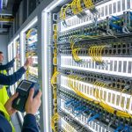
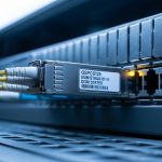
Consider a regional operator running a 3-tier data center and metro edge design for a 5G network. At the cell site aggregation layer, they use 48-port 10G switches feeding ring-based transport. In one rollout, each leaf cabinet connects to a metro aggregation switch over single-mode fiber at an average of 6.5 km, with seasonal temperature swings from -5 C to +45 C. Over time, they saw intermittent CRC errors on a small subset of links that were “within budget” during acceptance testing.
After replacing those suspect paths with adaptive optical transceivers (same wavelength class and connector type, deployed as the vendor-recommended part for that switch), the operator monitored DOM and interface counters for four weeks. The links that previously showed bursts of errors during the warmest afternoon windows stabilized, with Rx power variations shrinking and error counters returning to a near-zero baseline. The key operational win was not just that the link survived; it was that failure became less correlated with temperature and maintenance cycles.
This scenario is common in 5G network operations: fronthaul and backhaul are engineered for performance, but real-world variability taxes margin. Adaptive optics can provide an extra layer of tolerance, especially when the fiber plant is already installed and hard to re-engineer.

Selection criteria checklist for adaptive transceivers
Engineers often buy optics by reach and price, then discover incompatibilities during staging. For adaptive optical transceivers in a 5G network, use this ordered decision checklist to reduce rework and avoid link surprises.
- Distance and optical budget: Confirm connector loss, splice loss, and worst-case fiber attenuation. Include aging assumptions and patch panel penalties.
- Data rate and standard alignment: Match the Ethernet rate to the switch port capabilities and ensure compliance with IEEE 802.3 optical PHY expectations for that interface.
- Switch compatibility and vendor lock-in risk: Validate with the switch vendor’s optics compatibility list when available. If you go third-party, confirm both the electrical interface and DOM behavior.
- DOM support and telemetry granularity: Ensure the module exposes Tx power, Rx power, temperature, and alarm thresholds. For operational reliability, you need counters that correlate with optics.
- Operating temperature range: Prefer extended temperature variants for outside plant cabinets. A commercial module might pass in a lab and degrade prematurely in a hot enclosure.
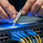
- Connector and cleaning strategy: Adaptive optics do not replace good fiber hygiene. Choose LC hardware that matches your patch panels and enforce cleaning with inspection.
- Failure mode behavior: Ask for guidance on how the module behaves during laser faults, fiber faults, and high-loss events. Your monitoring should catch it quickly.
When you evaluate part numbers, look for real-world track record and clear datasheet language. If a datasheet is vague about power control ranges or DOM alarms, treat that as a risk factor in critical 5G network paths.
Common mistakes and troubleshooting in adaptive 5G optics
Adaptive optical transceivers reduce marginal-link failures, but they do not eliminate the need for correct installation and monitoring. Below are frequent field failure modes, the root cause, and practical fixes.
“It passed acceptance, but fails later”
Root cause: The link budget was evaluated under optimistic conditions (low patch-panel loss, clean connectors) and then drifted due to contamination or aging splices. Adaptive optics may help, but if loss exceeds the module control range, errors still appear.
Solution: Re-measure end-to-end power using a calibrated optical power meter and verify connector cleanliness with an inspection scope. Compare current Rx power against DOM history to detect slow degradation.
DOM alarms are ignored, so real faults become “mystery CRC spikes”
Root cause: Teams see CRC or FCS counters but do not correlate them with DOM alarms such as high Tx bias, low Rx power, or temperature excursions. The optics layer provides early warnings.
Solution: Configure syslog or telemetry collection for DOM alarms, then create a correlation dashboard: time-aligned DOM thresholds vs interface error bursts.
Incompatible optics ecosystem across vendor platforms
Root cause: Some switch platforms enforce strict optics parameters or interpret DOM fields differently. A module may light but not operate within the expected margin, especially if adaptation behavior differs from what the switch expects.
Solution: Use the switch vendor’s validated optics list when possible. If you must use third-party parts, stage a small pilot and verify not only link up/down behavior but also stable error counters and DOM telemetry patterns.
Mis-matched fiber type or wrong transceiver class
Root cause: Multimode vs single-mode mismatches can look like “weak but link-up” behavior, then degrade quickly with temperature and connector changes.
Solution: Confirm fiber type labels and test with an OTDR or wavelength-specific power checks. Verify the module wavelength (for example, ~850 nm vs ~1310 nm) matches the fiber plant.
Cost and ROI note for 5G network operators
Adaptive optical transceivers typically cost more than baseline fixed-power modules, but the ROI can be compelling when you account for truck rolls, maintenance downtime, and the cost of repeated troubleshooting. In many enterprise and metro deployments, OEM-branded transceivers can run roughly $80 to $250 per 10G-class module depending on reach and temperature grade, while third-party alternatives may be $40 to $150 if they are properly validated for your switch. For higher-speed classes, pricing scales upward significantly.
TCO should include optics failure rates, cleaning supplies, inspection labor, and the operational time to investigate error bursts. A common outcome in 5G network operations is that adaptive optics reduce the frequency of marginal-link incidents, which lowers mean time to repair and prevents service degradation during seasonal stress. Still, operators should not treat adaptation as a substitute for fiber hygiene and correct loss budgeting.
FAQ: Adaptive optical transceivers for a 5G network
Which parts of a 5G network benefit most?
Adaptive optics are most valuable where fiber loss is variable or where you cannot easily rework the plant: metro edge backhaul, fronthaul aggregation corridors, and cell-site cabinets with frequent maintenance. They also help when temperature swings are significant and when you need better stability margin without re-architecting transport.
Do adaptive modules replace fiber inspection and cleaning?
No. Connector contamination is still one of the highest-probability causes of link instability. Adaptive control can mask mild issues by compensating power, but heavy contamination or severe connector mismatch will exceed the module’s control range.
How can I verify adaptive behavior during acceptance testing?
Log DOM telemetry and interface error counters while you introduce controlled attenuation (for example, adding known loss via attenuator or controlled patch changes). Look for a consistent Tx power response to Rx power changes while maintaining low BER/CRC errors.
Will third-party optics work on my switch?
Sometimes, but you must validate compatibility. Check for DOM support, wavelength class, and whether the switch enforces optics parameters beyond basic link-up. A small pilot with telemetry validation is the safest approach.
What standard should I reference when designing the optical layer?
For Ethernet over fiber, IEEE 802.3 defines PHY behavior and optical link expectations. For operational practices, also follow ANSI/TIA guidance on fiber cabling standards and loss testing workflows, and rely on vendor datasheets for module-specific limits.
What monitoring should I deploy for a 5G network?
At minimum, collect interface CRC/FCS counters and DOM alarms for Tx power, Rx power, and temperature. For proactive operations, set alert thresholds that trigger before errors spike, then correlate alerts to maintenance logs and environmental conditions.
Adaptive optical transceivers can materially improve the reliability of a 5G network by adding closed-loop stability and better observability, especially in deployed fiber plants with real variability. Next, review your current optical budget and telemetry coverage, then validate candidate modules with a short pilot before scaling across your transport rings.
5G transport network design
Author bio: I have deployed Ethernet over fiber links for metro and access networks, including hands-on optics validation with DOM telemetry and link-budget verification. I write from field test experience: measuring power, correlating error counters, and tuning monitoring for operational resilience.
Sources: [Source: IEEE 802.3] [Source: ANSI/TIA fiber cabling test and loss practices] [Source: Vendor transceiver datasheets and DOM documentation]