400G optical networking transceivers: the edge reality check

If you are upgrading an edge site to 400G, the hard part is rarely “will it light up,” it is matching the optical networking transceiver format, reach, and power to your switch and fiber plant without surprise incompatibilities. This article helps network engineers and field technicians compare QSFP-DD and OSFP style 400G optics, then choose the right reach and interface type for real deployment constraints. You will get practical selection criteria, common failure modes, and a decision matrix you can use during procurement and site acceptance testing.
QSFP-DD vs OSFP for 400G: performance and power tradeoffs
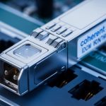
In optical networking, physical form factor drives thermal design, airflow requirements, and how the switch ASIC expects to manage optics. QSFP-DD commonly appears in 400G Ethernet ports where vendors want higher density with standardized lane mapping, while OSFP is often selected for high-power modules or where the chassis airflow and port layout favor its thermal envelope. In both cases, the underlying line coding and Ethernet framing must align with the switch’s port configuration.
From an engineering standpoint, your “performance” is a combination of optics reach (fiber attenuation tolerance and link budget), wavelength (for multimode vs single-mode), and receiver sensitivity. Most 400G deployments target either 400GBASE-SR8 over OM4/OM5 multimode, or 400GBASE-LR8 over single-mode with different spans. IEEE 802.3 defines the Ethernet optical link types and lane behavior; vendor datasheets then publish the exact supported distances and optics power.
| Category | QSFP-DD 400G (typical) | OSFP 400G (typical) |
|---|---|---|
| Target Ethernet types | 400GBASE-SR8, 400GBASE-LR8 | 400GBASE-SR8, 400GBASE-LR8 |
| Wavelength / media | SR8: 850 nm multimode; LR8: ~1310 nm single-mode | Same wavelength families, depends on SKU |
| Reach (examples) | SR8: ~100 m on OM4, up to ~150 m on OM5 (SKU dependent) | SR8: similar reach when specified for the same standard |
| Connector style | LC duplex or MPO/MTP (SKU dependent) | MPO/MTP common for SR8; LC options exist per vendor |
| Power budget | Lower to moderate module power; depends on vendor and cooling | Often designed for higher power envelopes; depends on airflow |
| DOM support | Typically supported via I2C/SFF-8636 style monitoring | Typically supported; verify vendor DOM map |
| Operating temperature | Usually industrial or commercial variants; verify exact SKU | Same; verify industrial vs commercial |
For reference, IEEE 802.3 specifies the optical link classes and how 8 lanes map for 400GBASE-SR8 and 400GBASE-LR8. Source: IEEE 802.3 Vendor datasheets then specify link budgets, receiver sensitivity, and maximum optical launch power. In field work, I treat those datasheet numbers as “hard constraints,” because real edge sites rarely have perfect connectors, clean MPO polarity, or ideal fiber cleaning discipline.
Pro Tip:
Before you compare QSFP-DD and OSFP on spec sheets, confirm your switch’s transceiver compatibility matrix and the chassis airflow assumptions. I have seen links fail only after a door was closed and the fan curve changed, because the module’s thermal limit was reached even though the link budget looked perfect on paper.
Reach planning: SR8 multimode vs LR8 single-mode
Edge networks are messy: patch panels get reworked, MPO trunks are re-terminated, and “short” runs become long due to cable management. For 400G optical networking, your choice often comes down to whether your site uses multimode (SR8) or single-mode (LR8), and whether the fiber plant is OM4, OM5, or true single-mode with predictable attenuation. If you have OM4/OM5 and you can keep MPO handling disciplined, SR8 can be cost-effective and fast to deploy. If you need longer reach, single-mode LR8 is usually the safer operational path.
In a typical acceptance test, I measure end-to-end fiber loss using an OTDR or a certified loss tester, then compare worst-case attenuation to the module’s stated link budget. For SR8, you must also account for differential mode delay and modal bandwidth limits, which are why OM5 can outperform OM4 for certain 850 nm channel plans. For LR8, connector cleanliness and back reflections matter more than people expect; a single dirty LC can cause intermittent errors that look like “bad optics” during troubleshooting.
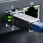
Compatibility and DOM: avoiding the “it clicks but won’t pass traffic” trap
Optical networking compatibility is not just “the module fits.” Switch vendors often implement strict checks: vendor ID, DOM format, and sometimes lane-to-lane mapping expectations. Many modern switches rely on standardized digital optical monitoring, but the DOM memory map and alarm thresholds can still differ across third-party manufacturers. If your edge site requires fast spares replacement, you need to minimize the risk that an approved transceiver behaves differently across chassis revisions.
During deployments, I run a structured checklist: confirm the exact port type (for example, 400G breakout mode behavior), verify the transceiver standard advertised by the switch, and validate DOM telemetry after link establishment. If the module reports temperature, bias current, and received power within expected ranges, then I move to error counters (CRC, FEC status where applicable) and only then start higher-level network verification. IEEE 802.3 defines the Ethernet physical behaviors, but the switch’s optics control plane is the practical gatekeeper.
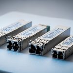
Cost and ROI: OEM vs third-party optics in edge environments
Budget pressure is real at the edge, especially when you need spares for multiple sites. OEM optics can cost more upfront, but they often reduce operational risk because they are validated against that switch model’s optics control requirements and thermal behavior. Third-party optics can be cheaper per port, yet the total cost of ownership depends on how often you face compatibility friction during change control, and how quickly your team can validate DOM and error performance on-site.
As a rough field range, many 400G SR8 optics land in the low hundreds of USD per unit for some OEM channels, while third-party options can be meaningfully lower, depending on vendor, reach, and certification. For LR8 single-mode optics, pricing is often higher due to optics complexity, and spares are typically more expensive. My ROI model is simple: compare unit price plus expected validation labor time plus the cost of any downtime during site cutover; the “cheapest” module wins only if it passes compatibility and acceptance without extra truck rolls.
| Decision factor | OEM optics | Third-party optics |
|---|---|---|
| Upfront cost | Higher | Lower |
| Compatibility likelihood | Higher with vendor matrix | Varies; needs validation |
| DOM telemetry consistency | Typically aligned with switch expectations | May require extra monitoring validation |
| Spare strategy | Easier cross-site standardization | Risk of “works here, fails there” if not standardized |
| TCO sensitivity | Best when downtime is expensive | Best when validation processes are mature |
For concrete examples of reputable product families, you will often see 400G SR8 and LR8 optics from brands such as Finisar/Lumentum and OEM channel partners, with SKUs like Finisar FTLX8571D3BCL (100G-class examples exist, but validate exact 400G part numbers for your target). For third-party compatibility, FS.com and similar suppliers publish 400G optics listings with reach and DOM details; verify that the exact part number matches the switch vendor and port type you are using. Source: FS.com transceiver catalog and Source: Lumentum optical modules.
Selection criteria checklist: what engineers weigh during procurement
Use this ordered checklist in optical networking projects so procurement, cabling, and acceptance testing stay aligned. I use it like a field-ready worksheet before ordering any transceiver batch for an edge site.
- Distance and fiber type: pick SR8 vs LR8; confirm OM4 vs OM5 vs single-mode with measured loss.
- Switch and chassis compatibility: check the vendor transceiver matrix for your exact switch model and port number range.
- Form factor constraints: confirm QSFP-DD vs OSFP support, plus required airflow clearance and thermal envelope.
- Connector and polarity: ensure MPO/MTP polarity and cleaning method match your patching standard.
- DOM and telemetry: verify DOM support and whether your monitoring system expects specific thresholds.
- Operating temperature: confirm commercial vs industrial SKUs for outdoor or poorly cooled edge rooms.
- Vendor lock-in risk: decide whether you need OEM-only spares or if third-party modules are acceptable with your validation playbook.
- Spare strategy: order spares based on MTBF expectations and the blast radius of a failed module at that site.
Common mistakes and troubleshooting tips in 400G optical networking
Most 400G optical networking issues are not “mystical”; they are predictable failure modes that show up during power, thermal, or fiber handling steps. Here are the ones I see most often, with root cause and field solution.
- Mistake: MPO polarity mismatch. Root cause: incorrect A-to-B orientation or swapped polarity jumpers causing high lane errors. Solution: re-verify polarity using a polarity tester, then re-terminate or re-patch with the documented standard for your vendor patching scheme.
- Mistake: Dirty connectors at first power-on. Root cause: residue on LC or MPO endfaces leading to intermittent receiver overload or elevated BER. Solution: clean using approved swabs and inspection scope; then re-seat the module and re-check receive power and error counters.
- Mistake: Thermal throttling after door closure. Root cause: airflow reduction increases module temperature beyond spec, causing link flaps. Solution: confirm fan curve behavior, measure inlet and outlet temps, and ensure the module cage has unobstructed airflow; upgrade to an industrial-rated SKU if the room runs hot.
- Mistake: DOM alarms ignored during burn-in. Root cause: monitoring alerts exist but are not wired into your on-call process, so marginal optics degrade silently. Solution: baseline DOM readings at commissioning, set thresholds in your monitoring system, and schedule a short burn-in window before cutover.
Real-world deployment scenario: 400G optics in a 3-tier edge
In a 3-tier edge data center design, imagine 48-port 400G uplinks from a top-of-rack layer to an aggregation layer, with each rack group needing 4 x 400G links for east-west traffic. At one site, we had OM4 fiber for short runs (under 120 m) and single-mode for a few longer cross-room paths. We standardized on SR8 for the OM4 segments using QSFP-DD modules, and LR8 for the single-mode segments using OSFP where the chassis airflow profile favored it. During acceptance, we validated receive power per lane, ensured error counters stayed at baseline over a 30-minute burn-in, and confirmed DOM telemetry thresholds matched the switch vendor expectations.
The operational win was consistency: field teams could carry pre-approved spares, and monitoring alarms were tuned to real DOM behavior rather than generic defaults. The risk we mitigated upfront was compatibility drift between chassis revisions; we used the vendor matrix for the exact switch platform and avoided “close enough” part numbers.
Which Option Should You Choose?
If you need the best fit for dense, standardized port layouts and your switch clearly supports QSFP-DD optics with validated SR8/LR8 SKUs, choose QSFP-DD for multimode edge segments where reach is within OM4/OM5 limits. If your edge chassis favors higher thermal envelopes, or your vendor matrix points you to OSFP for the exact port type and reach, choose OSFP even if the module cost is slightly higher.
For engineers optimizing for speed of deployment and fewer surprises, prioritize switch compatibility and measured link budget over form factor preference. If your team has strong validation processes and you can enforce connector cleaning and polarity discipline, third-party optics can reduce costs, but only after you test the exact part numbers in a pilot rack.
FAQ
Q: What does IEEE 802.3 cover for 400G optical networking?
IEEE 802.3 defines the 400G Ethernet physical layer standards such as SR8 and LR8, including lane mapping and optical behavior expectations. It does not guarantee switch vendor compatibility, so you still must follow the switch optics matrix. Source: IEEE 802.3
Q: How do I decide between SR8 and LR8 for an edge site?
Start with measured fiber attenuation and connector loss, then compare against the module’s stated link budget. If your runs exceed the multimode reach budget, or if fiber plant quality is uncertain, single-mode LR8 is usually the safer choice.
Q: Are QSFP-DD and OSFP interchangeable on the same switch?
No. Even when both support 400G standards, the switch port design and thermal envelope may require one specific form factor. Always verify the exact port type and transceiver matrix for your switch model.
Q: What is DOM, and why does it matter during troubleshooting?
DOM provides digital telemetry such as temperature, bias current, and received optical power. If DOM thresholds or alarm interpretations differ, you can miss early degradation signals; field teams benefit from baselining DOM readings during commissioning.
Q: Can I use third-party optics to cut cost?
Often yes, but only if the part numbers are validated against your switch model and you run an acceptance test plan that includes DOM verification and error counter baselining. Treat compatibility as a process, not a promise.
Q: What should I inspect first when a 400G link will not come up?
Begin with fiber polarity and connector cleanliness, then confirm the transceiver standard is enabled on the switch port. After that, check DOM telemetry and thermal conditions, because some failures only appear after the chassis reaches steady-state airflow.
If you want a practical follow-on step, use 400G fiber polarity and cleaning standards to tighten your acceptance testing for MPO and LC links. With consistent fiber handling plus validated transceiver selections, your 400G optical networking upgrades become predictable instead of stressful.
Author bio: I am a field-focused photographer and network engineer who documents optical deployments with hands-on optics inspection, link testing, and switch-level acceptance workflows. I write from the perspective of the person standing in the rack aisle during cutover, when details like polarity and thermal behavior decide success.