When a 400G upgrade stalls, it is often not the switch or fiber plant, but the optics lane mapping, DOM behavior, and reach class mismatch. This reference helps field engineers and network planners choose the right `400G 8-lane SFP` style transceiver for QSFP-DD800-class 400G deployments, and avoid the failure modes that show up after install. You will get a spec comparison table, a distance and compatibility checklist, and concrete troubleshooting steps from hands-on optics bring-up.

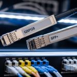
What “400G 8-lane SFP” means in practice
In 400G coherent and direct-detect ecosystems, the “8-lane” idea typically refers to splitting the payload across eight optical lanes rather than four, reducing per-lane speed and easing optics signal integrity requirements. For direct-detect 400G over short reaches, the common lane mapping is aligned with vendor implementations that also appear in QSFP-DD800-class optics families. In the field, your real concern is whether the module’s lane/bus mapping matches the host port expectations and whether the transceiver reports the correct capabilities via Digital Optical Monitoring (DOM).
Compatibility reality: host port mode matters
Many 400G hosts can run multiple optics profiles (for example, different modulation formats or lane maps). During commissioning, verify the port optics profile in the switch CLI and confirm the transceiver enumerates cleanly. If the switch expects a specific lane assignment, a “compatible-looking” module can still light up at low diagnostics but fail BER targets under load.
Key specs to verify before you buy
Engineers often compare only wavelength and reach. For 400G 8-lane optics, you must also verify connector type, electrical interface class, output power, receiver sensitivity, DOM support, and the temperature range that matches your rack environment. Below is a practical comparison framework for common 400G short-reach options that behave similarly to QSFP-DD800-class operational profiles.
| Parameter | 400G 8-lane SFP (example short-reach profile) | Typical QSFP-DD 400G-class reference |
|---|---|---|
| Data rate | 400G total (8 lanes) | 400G total (module-dependent lane map) |
| Lane concept | 8-lane mapping; per-lane rate reduced vs 4-lane | May be 4-lane or 8-lane depending on vendor profile |
| Wavelength | Usually 850 nm for short-reach direct-detect variants | Commonly 850 nm in SR classes |
| Reach class | Typical SR reach targets (verify OM4/OM5 budget) | Vendor reach targets; confirm OM4 vs OM5 support |
| Connector | Often LC duplex or MPO-style depending on form factor | Often MPO-12 or MPO-16 in higher-density families |
| DOM | Required for alarms and diagnostics | Required (vendor-specific thresholds) |
| Operating temperature | Confirm 0 to 70 C or -5 to 85 C variant | Confirm same temperature class to match installation |
| Electrical interface | Host-specific 400G lane/bus mapping | Host-specific profile; must match port configuration |
For standards context, validate that the transceiver behavior aligns with relevant Ethernet optics guidance and host port expectations. For general Ethernet physical layer references, see [Source: IEEE 802.3] and vendor datasheets for the exact transceiver family and supported DOM registers. External authority: [[EXT:https://standards.ieee.org/standard/]] for IEEE 802.3 navigation.
Distance and fiber budget: how to avoid reach surprises
For SR links, the reach outcome is dominated by fiber type (OM4 vs OM5), patch cord quality, insertion loss, and system margin under temperature. In one deployment, a data center corridor used OM4 with older patch cords; link bring-up passed initial diagnostics, but sustained traffic caused increasing error counts after thermal ramp. The fix was replacing patch cords and rebalancing the loss budget, not swapping the switch.
Field method: verify the loss budget and DOM thresholds
- Confirm fiber type and grade in the cable plant documentation (OM4 vs OM5).
- Measure end-to-end insertion loss using an OTDR or certified loss meter.
- Check patch cord and connector cleanliness; MPO/LC contamination can mimic “bad optics.”
- During traffic test, monitor DOM: receive power and vendor-defined warning thresholds.

Pro Tip: In many 400G ports, the transceiver can “enumerate” successfully while still running outside the vendor’s intended power margin. Always validate with a traffic test and watch DOM receive power trends over temperature, not just the link-up status LED.
Selection criteria decision checklist (engineers actually use)
Use this ordered list to reduce rework and avoid incompatible optics profiles.
- Distance and fiber class: OM4/OM5, connector type, and measured insertion loss.
- Host port compatibility: confirm the switch model supports the exact optics profile and lane map.
- Switch optics profile setting: ensure the port is configured for the correct 400G mode.
- DOM support: verify alarms, vendor-specific thresholds, and register accessibility.
- Operating temperature: match transceiver temperature class to rack airflow and ambient extremes.
- Vendor lock-in risk: check optics compatibility lists and return policies for third-party modules.
- Connector and patch strategy: ensure cabling (LC duplex vs MPO) matches the planned breakout and patching standard.
Common mistakes and troubleshooting tips
Below are failure modes seen during 400G optics commissioning. Each includes a root cause and a practical fix.
Link comes up, but BER/CRC errors spike under load
Root cause: reach budget exceeded or patch cord loss too high; per-lane power margin collapses during sustained operation. Solution: measure insertion loss end-to-end, replace patch cords, and confirm receive power stays within vendor-defined limits.
Port shows “unsupported optics” or stays in err-disable
Root cause: port profile mismatch (lane map or electrical interface mode) or DOM capability mismatch. Solution: set the port to the correct optics mode in the switch, power-cycle the port, and confirm DOM enumerates with expected vendor ID fields.
Intermittent link flaps that correlate with airflow or cleaning schedules
Root cause: optical connector contamination (especially MPO/LC endfaces) causing transient signal degradation. Solution: inspect and clean with approved lint-free procedures, re-seat the module, and re-test with a stable traffic generator.
Wrong transceiver temperature class for the environment
Root cause: transceiver rated for 0 to 70 C deployed in a hot aisle or poorly ventilated cabinet. Solution: move to a supported temperature class variant and validate ambient and airflow with a rack thermal survey.
Deployment scenario: 400G leaf-spine upgrade with lane-map constraints
In a 3-tier data center leaf-spine topology with 48-port 400G-capable ToR switches, we upgraded 12 uplinks per leaf to 400G direct-detect short reach. The fiber plant used OM5 in new zones and OM4 in legacy zones, with patch cords that were not standardized across vendors. During the first rollout wave, two leaves showed CRC error growth after thermal ramp; DOM indicated receive power drifting toward the lower threshold. Replacing patch cords in the OM4 zones and aligning the port optics profile eliminated errors without changing optics hardware.

Cost and ROI note: OEM vs third-party optics
Typical street prices vary widely by wavelength, reach, and vendor ecosystem. As a planning baseline, third-party 400G-class optics often land in the mid-hundreds to low-thousands of USD per module, while OEM-branded equivalents can be higher with tighter compatibility guarantees. TCO usually favors optics that reduce truck rolls: higher module price is justified if it lowers failure rate and avoids downtime during maintenance windows. Track mean time to replace (MTTR) and do not ignore the engineering time cost of compatibility validation across switch firmware versions.
For procurement and compatibility strategy, cross-check switch vendor compatibility lists and module datasheets before standardizing a part number. When possible, pilot a small batch and validate with traffic and DOM monitoring.
FAQ
What should I confirm about a 400G 8-lane SFP before installation?
Confirm the host port supports the exact 400G optics profile and lane mapping, and verify DOM support. Also validate fiber type and measured insertion loss against the vendor reach budget.
Can I use third-party modules with QSFP-DD800-class systems?
Sometimes, but compatibility is not universal across switch models and firmware revisions. Use the vendor compatibility list, run a pilot, and confirm DOM enumerates correctly.
How do I tell if reach is the issue versus a bad transceiver?
Check DOM receive power trends during a traffic test and compare against vendor warning thresholds. Then measure end-to-end insertion loss and clean/reseat connectors; if power margin improves after cabling fixes, optics were likely fine.
Why does the link come up but errors appear later?
Power margin can be marginal at initial conditions but fail under temperature and sustained load. Monitor BER/CRC counters and DOM over time rather than relying on link-up status.
What connector problems are most common for 400G short reach?
Contamination and poor seating on LC or MPO endfaces are common culprits. Use approved cleaning tools, inspect with a scope, and replace damaged patch cords.
Where can I find authoritative standards and guidance?
Start with IEEE 802.3 references for Ethernet physical layer concepts and then rely on specific vendor datasheets for the transceiver and host port. Use the switch manufacturer’s optics compatibility documentation for the final word.
Next step: build a short pilot plan using the checklist above, then standardize the optics part number only after DOM and traffic validation. If you