You are planning a high-density upgrade and the lab test results do not match field reality: link flaps, unexpected power draw, and optics that will not negotiate cleanly. This guide helps network and field engineers select and validate a 224G PAM4 transceiver for the 1.6T transceiver roadmap, with concrete compatibility checks, measured deployment practices, and troubleshooting. It is written for teams standardizing leaf-spine and spine-upgrade fabrics where optics spend is significant and downtime costs are measurable.
Where 224G PAM4 fits in the 1.6T transceiver roadmap
The “1.6T roadmap” framing is about scaling total system bandwidth using higher-order modulation, tighter lanes per port, and improved DSP/CTLE/DFE behavior. In practice, a 224G PAM4 transceiver is used as a building block for next-generation 800G class optics (often via coherent or advanced multi-lane architectures) and for early transitional designs that need more throughput per fiber pair than legacy NRZ. The key operational point is that PAM4 links are more sensitive to dispersion, connector cleanliness, and host-side signal integrity than many teams expect.
From an engineering perspective, you should treat the optics as a coupled system with: host retimer/linear equalization, fiber plant, patch panel loss, and the transceiver’s own RX sensitivity and jitter tolerance. Vendor datasheets may show “reach” under ideal test conditions, but real plants include insertion loss variance across harnesses, and additional reflections from mismatched connectors. IEEE 802.3 defines Ethernet PHY behavior; the optics must also meet the applicable electrical interface expectations for the host platform. For standards context, use IEEE 802.3 Ethernet standard overview and vendor interface guidance from your switch OEM.
Pro Tip: In field deployments, “link up” is not the same as “stable under temperature cycling.” Always validate with a BER or FEC error counter over at least one full HVAC cycle, because PAM4 jitter margins can compress as module temperature and host clock distribution drift.
Core technical specs you must verify before purchase
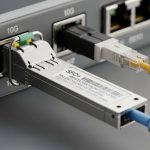
Selection starts with matching the transceiver’s optical and electrical parameters to your switch and fiber budget. Even when two modules are both labeled “224G PAM4,” the details differ: wavelength band, reach class, connector type, optical power levels, and whether the module supports digital optical monitoring (DOM) with your host. The table below summarizes the key fields engineers should compare across candidates and SKUs.
| Spec category | What to check | Typical values to expect (examples) | Why it matters in PAM4 |
|---|---|---|---|
| Data rate | Line rate and encoding mode | 224G PAM4 class | Determines DSP equalization needs and host lane mapping |
| Wavelength | Band and center wavelength | Commonly C-band or vendor-specific | Impacts dispersion and filter alignment with plant and WDM components |
| Reach | Rated distance class | Vendor-defined reach (short/extended) | Directly tied to power budget and dispersion tolerance |
| Connector | Physical interface | Common: LC or MPO variants | Connector geometry affects reflections and return loss |
| Optical power | TX output and RX sensitivity | Check min/max and margins | Defines whether FEC can correct residual errors over aging fiber |
| DOM / management | Telemetry availability | Temperature, bias current, optical power, alarms | Enables proactive maintenance and safe thresholding |
| Operating temperature | Module grade | Often commercial vs extended industrial | PAM4 margins change with temperature; verify host airflow assumptions |
| Power consumption | TX/RX module draw | Vendor-specific, verify per-port budget | Overdraw can trigger PSU derating or thermal throttling |
| Electrical interface | Lane count, signaling, and retimer expectations | Host-dependent electrical spec | Incorrect host settings can cause intermittent training failures |
For concrete product examples and typical optical parameters, consult the exact datasheet for your candidate transceiver. If you are comparing third-party optics, confirm that the vendor explicitly states compatibility with your switch model and the specific firmware train used in your environment. Use the switch OEM “optics compatibility list” as the top authority, then cross-check with the optics datasheet. For general optics interface expectations, start with ITU grid and wavelength guidance when WDM is present, and with the relevant IEEE PHY behavior for Ethernet.

Engineering a reliable link budget for PAM4 at real distances
Do not rely on “rated reach” alone. Build a fiber budget that includes patch cords, splices, and any passive components (such as splitters or WDM mux/demux). Then add an engineering margin for aging and connector cleaning variability. A field-tested approach is to model worst-case insertion loss and worst-case return loss, then verify with live BER counters.
Step-by-step link budget workflow
- Determine the required lane mapping for your switch port type and confirm the optics electrical interface matches the host expectation for training.
- Measure plant loss using an OTDR or calibrated power meter at the wavelength band used by the module.
- Include harness loss from patch cords and any breakout cables. In many data halls, harnesses contribute more than the fiber run itself.
- Account for reflection risk by checking connector cleanliness and return loss targets. PAM4 links are less forgiving of multipath and reflections.
- Validate with FEC/BER telemetry for at least 24 hours and across a temperature change event.
Reach validation metrics that matter
Engineers should monitor link stability indicators such as FEC corrected error counts, uncorrectable error counters, and any “loss of signal” or “link training failed” events. If the module supports DOM, capture temperature, bias current, and optical power in a time series. A stable PAM4 deployment typically shows consistent optical power within vendor tolerance and no bursts of corrected errors correlated with temperature ramps.
Deployment scenario: 3-tier data center upgrade with 224G PAM4
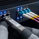
Consider a 3-tier leaf-spine topology in a facility running 48-port 10G ToR switches and 12-port 400G spine uplinks, where the team upgrades the spine to higher throughput and adds new high-density aggregation blades. You plan to deploy 32 optics per pod during a maintenance window, with each spine line card expecting a specific optics electrical profile. The fiber plant includes 20 meters of OM4 multimode patching in the row-to-row segment and 300 meters of single-mode in the trunk segment, with two patch panel interconnects and roughly 6 splices per path.
In this environment, the biggest operational wins come from standardizing optics and fiber hygiene. The team pre-cleans connectors, uses consistent patch cord grades with known insertion loss, and schedules a post-install verification sweep using a power meter and OTDR. During commissioning, engineers run traffic with a sustained load profile (for example, 60% utilization for 12 hours) while collecting DOM telemetry and checking FEC error counters for any drift. This is where 224G PAM4 transceiver selection affects uptime: incorrect module SKUs or marginal link budgets can pass early tests but fail during heat soak.

Selection criteria checklist engineers use on the floor
Use this ordered checklist to reduce rework and avoid incompatible transceivers. It is designed for procurement and field acceptance testing, not just lab demonstrations.
- Distance and plant loss: confirm the module reach class against measured insertion loss at the correct wavelength band, including harnesses.
- Switch compatibility: verify the transceiver appears on the OEM compatibility list for your exact switch model and firmware release.
- DOM support and thresholds: ensure the host reads DOM alarms correctly; confirm supported telemetry fields and calibration behavior.
- Operating temperature and airflow: match module temperature grade to your cabinet airflow assumptions; verify no thermal throttling under peak load.
- Power budget and PSU derating: compute per-port and per-card draw; ensure the chassis thermal design accounts for transceiver power.
- Vendor lock-in risk: if you choose an OEM-locked option, quantify replacement cost and lead time; if you choose third-party, require documented compatibility and warranty terms.
- FEC and error performance: require acceptance criteria using BER or FEC counters under representative traffic patterns.
- Return loss and connector ecosystem: standardize on the same connector type and cleaning workflow across the deployment team.
Common pitfalls and troubleshooting tips for 224G PAM4 links
Even well-chosen optics can fail in the field due to plant and configuration issues. Below are frequent failure modes with root cause and actionable remediation.
Pitfall 1: “Link up” but traffic errors spike
Root cause: marginal optical power budget or excessive reflections from dirty or worn connectors, causing PAM4 equalization to operate near its limit. This often shows up as bursts of corrected errors that correlate with temperature changes.
Solution: clean and inspect connectors with a fiber microscope, replace patch cords, then re-measure optical power at the receiver. Validate under a controlled temperature ramp and confirm FEC counters remain stable.
Pitfall 2: Intermittent training failures after reboot
Root cause: host-side settings mismatch, such as lane mapping or electrical equalization mode not aligned with the transceiver’s expected signaling. Sometimes this happens after a firmware update that changes default PHY parameters.
Solution: lock firmware versions during acceptance testing, confirm port configuration templates match the optics type, and use DOM/host logs to identify whether the failure is “LOS,” “training failed,” or “signal quality below threshold.”
Pitfall 3: Unexpected thermal throttling or link drops at peak load
Root cause: insufficient airflow, blocked cable trays, or transceiver power draw exceeding the chassis thermal assumption. PAM4 modules can be more sensitive because DSP behavior changes with temperature.
Solution: verify cabinet airflow path, check fan curves, and compare measured module temperature via DOM against the vendor’s recommended operating range. If needed, reseat optics, improve cable routing, and rebalance load across line cards.
Pitfall 4: DOM alarms not triggering despite faulty optics
Root cause: host does not interpret DOM fields correctly for a third-party implementation, or thresholds are not mapped to your monitoring stack. Engineers then miss early warning symptoms.
Solution: during commissioning, deliberately induce a test condition (within safe limits) such as lowering optical power using a calibrated attenuator and confirm the host generates the expected alarm and log entry.
Cost, ROI, and compatibility tradeoffs
Pricing varies widely by reach class, brand, and whether the module is OEM-branded or third-party. As a practical planning range, many 224G-class PAM4 optics in early adoption cycles can cost from hundreds to low thousands of USD per module, with higher costs for extended reach, stricter binning, or integrated optics with enhanced DSP. Total cost of ownership depends less on purchase price and more on uptime risk, spare strategy, and labor time during replacement.
For ROI, compare at least three factors: (1) compatibility assurance (reduced truck rolls), (2) expected failure/return rate under your thermal and cleaning practices, and (3) power and cooling impact. If third-party modules lower purchase price but increase field failure probability, the labor and outage cost typically dominates savings. If you need a reference for Ethernet PHY behavior and operational constraints, use IEEE 802.3 documentation and follow OEM optics guidance for safety and interoperability. IEEE 802.3 working group resources can help you track relevant updates.

FAQ for buyers evaluating a 224G PAM4 transceiver
Which switch models should I validate first?
Start with your exact switch model and the firmware release that will run the deployment. OEM optics compatibility lists are the fastest way to avoid lane mapping and DOM interpretation issues. If you plan a third-party option, require documented compatibility for that specific firmware train.
How do I confirm the fiber plant can support PAM4 reliability?
Measure insertion loss and connector cleanliness, then validate with live FEC or BER counters under representative traffic. Do not stop at “link up”; PAM4 can look healthy initially and then degrade under temperature or after sustained load. Use DOM time series to correlate optical power and temperature with any error bursts.
Is DOM required, or can we operate without it?
DOM is strongly recommended because it provides actionable telemetry for early warning and incident response. Some hosts can run without DOM integration, but monitoring blind spots often increase mean time to repair. Ensure your monitoring stack understands the DOM alarm thresholds exposed by the module.
What operating temperature range should I plan for?
Use the module’s specified operating temperature grade and compare it to your cabinet airflow conditions. In field deployments, the hottest point is often near the exhaust side or behind dense cable bundles. Validate with DOM temperature logs during peak load and after a controlled power cycling event.
Can I mix vendors of 224G PAM4 transceivers in the same fabric?
Mixing is sometimes possible but increases the risk of inconsistent training behavior, alarm mapping, and optical power calibration. If you must mix, test each vendor with your full configuration and monitoring workflow, including error counter thresholds. For production, standardize on one validated SKU per port type.
What acceptance criteria should procurement require?
Require a defined link stability window (for example, 24 hours), acceptable FEC corrected error behavior, and confirmation that DOM alarms are correctly generated in your logs. Also include a thermal and reboot test because many PAM4 failures appear only after temperature cycling or host restarts.
If you want the next step, create a short “optics acceptance pack” for your team: measured link budget template, DOM alarm verification checklist, and a 24-hour stability test procedure. Then apply it consistently to every 224G PAM4 transceiver procurement cycle using how to build an optics acceptance test plan.
Author Bio: I have deployed high-density optical systems in production data centers, where PAM4 stability depends on measured budgets, connector hygiene, and host PHY settings. I write field-oriented guides grounded in vendor datasheets, IEEE 802.3 expectations, and operational acceptance testing results.