If you are upgrading a leaf-spine fabric, stretching metro links, or refreshing aging optics, the decision between 100G vs 400G impacts port density, power budgets, and upgrade schedules. This article helps network engineers and architects evaluate optical transceiver speeds from 100G to 400G with practical constraints like switch lane mapping, fiber reach, and DOM telemetry support.
100G vs 400G: What changes in real deployments
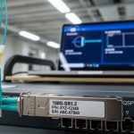
On paper, both 100G and 400G are “fast Ethernet” optics, but their internal lane and signal structures drive different hardware tradeoffs. Most 100G modules use a 10-lane or 4-lane architecture depending on the form factor (for example, QSFP28 or OSFP variants), while common 400G implementations are often 8-lane or 16-lane designs depending on the standard and module type (for example, QSFP-DD or OSFP-LR4/FR4 style families). The practical outcome: 400G reduces the number of switch ports you need for the same aggregate bandwidth, but it increases per-port optics cost and tightens compatibility requirements with the switch vendor’s lane breakout support.
IEEE 802.3 defines key Ethernet PHY behaviors; individual optics must also match the switch’s supported optic types and electrical interface. For baseline standards, reference [Source: IEEE 802.3]. For optical reach and performance expectations, vendor datasheets and transceiver test reports are critical because they capture real power consumption and receiver sensitivity targets.

Performance and optics specs: reach, wavelength, power, and temperature
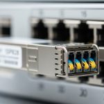
In the field, the “right” choice is usually defined by wavelength, reach, and operating temperature more than by marketing speed claims. For short-reach data center links, 100G frequently uses SR optics over multimode fiber (MMF), while 400G commonly uses higher-density SR variants over OM4/OM5—often with tight link budgets and strict MPO/MTP polarity handling. For longer reach, both can use coherent or PAM4-based approaches depending on the vendor, but typical non-coherent “LR4/FR4” style optics are where many engineers compare cost per link.
| Parameter | Typical 100G SR (MMF) | Typical 400G SR (MMF) |
|---|---|---|
| Data rate | 100 Gbps | 400 Gbps |
| Wavelength | 850 nm (MMF SR) | 850 nm (MMF SR) |
| Common reach | Up to 100 m on OM4 (varies by module) | Up to 100 m on OM4/OM5 (varies by module) |
| Connector | LC (often) or MPO (depends on form factor) | MPO/MTP (common for high-density SR) |
| Form factor | QSFP28 (common) | QSFP-DD or OSFP (common) |
| Power (typical) | ~2.5 W to 5 W | ~8 W to 12 W |
| Operating temperature | 0 to 70 C (commercial) or -40 to 85 C (extended) | 0 to 70 C or -40 to 85 C (module-dependent) |
| DOM telemetry | Often supported (I2C/MDIO via host) | Often supported; verify switch parsing |
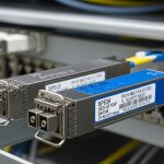
Concrete examples help anchor expectations. A Finisar FTLX8571D3BCL is an example of an 850 nm class optics family used for short reach in many vendor ecosystems (verify exact speed and reach from the datasheet). For 10G-to-100G scaling, Cisco and other vendors publish compatibility lists for specific part numbers such as Cisco SFP-10G-SR and higher-rate equivalents; for 400G, check the exact vendor module family supported by your switch line card. Always validate with your switch’s optics compatibility guide and the module datasheet power and temperature ratings.
Pro Tip: Before you buy, confirm whether your switch supports native 400G optic types on the target ports and whether it expects a specific MPO polarity or lane ordering. Many “it should work” failures come from lane mapping mismatches and polarity inversions, not from marginal optical power.
Cost and ROI: when 400G wins on total ports and power
Cost is not just the transceiver unit price; it is also the number of switch ports you must provision, the optics inventory you must stock, and the probability of field replacement. In many data center refresh cycles, 400G reduces port counts by 4x compared to 100G for the same aggregate throughput, which can translate into simpler cabling topology and fewer transceiver SKUs. However, 400G optics often cost significantly more per module, and the per-link power can be higher due to more complex modulation and optics internals.
Realistic budget planning: third-party 100G SR modules commonly land in the low tens of dollars to low hundreds depending on reach and brand; 400G SR modules often land in the hundreds to low thousands per module depending on OEM vs third-party and whether you need extended temperature. TCO also includes optics failures and downtime. If your MTBF assumptions are driven by the vendor’s qualification process, OEM modules can reduce risk at the cost of higher upfront spend, while third-party can cut CAPEX but may require stricter acceptance testing.
Power ROI should be calculated per delivered throughput. If a 400G port consumes, for example, ~10 W and a set of four 100G ports consumes ~4 W each, then raw optics power is roughly comparable, but switch port and line card utilization may differ. In constrained chassis designs, fewer active ports can reduce overall system power and cooling load. Still, you must verify with your specific switch platform power model and optics power draw from datasheets.

Compatibility and interoperability: the hidden make-or-break factor
Compatibility is where 100G vs 400G decisions frequently stall. Many switch vendors implement electrical lane maps and firmware checks that require specific optic families and sometimes specific vendor part numbers. A 400G module may physically fit, but the host may reject it if the module’s programming interface, DOM behavior, or supported PHY parameters do not match what the switch expects. This is why you should treat the switch optics matrix as the source of truth.
Key checks include: supported module form factor (QSFP28 vs QSFP-DD/OSFP), wavelength and reach class (SR vs LR4 vs FR4), and DOM support (temperature, supply voltage, bias current, received power). Also verify whether your switch supports breakout modes. For example, some 400G optics can be used in a native 400G port, while breakout into multiple 100G lanes may not be supported on all platforms. For DOM, confirm the switch correctly reads thresholds and that your monitoring system interprets the vendor-specific calibration fields.
Use authoritative references: [Source: IEEE 802.3] for Ethernet PHY framing expectations, plus your switch vendor’s optics compatibility guide and the transceiver datasheets for electrical/optical parameters. For additional practical compatibility context, consult reputable vendor documentation and field notes from major tech publications, but always validate against your exact switch model.
Selection checklist: choose 100G or 400G with fewer surprises
- Distance and fiber type: measure installed MMF/SMF length and verify OM4 vs OM5 and connector cleanliness; confirm real link budget.
- Switch compatibility matrix: confirm exact part numbers supported on your line cards and port types; do not rely on generic “QSFP-DD works” assumptions.
- Reach class and wavelength: pick SR for short MMF, LR/FR for longer distances, or coherent solutions for extreme reach; validate wavelength and power specs.
- DOM and telemetry: verify the switch can read DOM fields your NMS expects; ensure alarm thresholds align with your operational policies.
- Operating temperature: match commercial vs extended temperature requirements, especially for top-of-rack and hot-aisle exposure.
- Vendor lock-in risk: assess OEM vs third-party acceptance testing effort, warranty terms, and RMAs; plan a qualification test for any new vendor SKU.
- Power and thermal budget: use module power draw from datasheets and confirm chassis cooling headroom at your utilization level.
- Migration path: consider whether you need temporary 100G capacity while new 400G line cards arrive, and plan inventory accordingly.
Common pitfalls and troubleshooting tips
Pitfall 1: Port rejects the optic or stays down. Root cause is often switch firmware compatibility checks failing due to unsupported optic type, DOM behavior, or electrical lane mapping. Solution: verify the exact module part number is listed for your switch model and update switch firmware only if the vendor recommends it for that optic family.
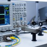
Pitfall 2: Link comes up but shows high errors or frequent flaps. Root cause commonly involves MPO/MTP polarity inversion, incorrect lane ordering, or a dirty connector causing receiver saturation or high BER. Solution: re-terminate or re-polish, clean with approved fiber cleaning tools, and validate polarity using an MPO polarity tester; then re-run BER counters.
Pitfall 3: Reach is shorter than expected after installation. Root cause is usually fiber plant assumptions failing: patch loss, bad splices, or using OM3/graded-index incorrectly for the chosen SR class. Solution: measure with an OTDR and verify end-to-end loss; compare the measured budget to the module’s datasheet link budget under your temperature range.
Pitfall 4: Monitoring shows “DOM present” but thresholds are wrong. Root cause is NMS mapping mismatches for vendor-specific DOM calibration fields. Solution: update your transceiver monitoring profiles and confirm alarm behavior in a controlled test before deploying broadly.
Which option should you choose?
Choose 100G when you are modernizing capacity incrementally, dealing with mixed generations of switch hardware, or optimizing for lower module cost and simpler compatibility. Choose 400G when you need higher aggregate throughput per switch row, want fewer ports for the same bandwidth, and have a clearly validated optics matrix for your specific switch platform.
Decision matrix (engineering view)
| Criteria | 100G | 400G |
|---|---|---|
| Port density requirement | Lower density | Higher density |
| Upfront optics CAPEX | Lower per module | Higher per module |
| Compatibility risk | Usually easier across platforms | Higher need for exact support |
| Cabling complexity | More fibers/ports | Often fewer ports but MPO handling |
| Power per delivered throughput | Often favorable depending on platform | Can be favorable; validate with chassis model |
| Operational telemetry | Widely supported | Supported but verify parsing and alarms |
Next step: build a small pilot with the exact transceiver part numbers you plan to deploy, measure link BER and DOM telemetry under your ambient temperature, and only then scale. If you are still mapping speeds across your portfolio, review How to choose fiber optic transceivers for high density data centers.
FAQ
Is 400G always better than 100G for data centers? Not always. 400G can reduce port count and improve scaling, but it increases compatibility requirements and may raise per-module cost. If your switch platform does not fully support the 400G optic family, 100G can be the safer operational choice.
What fiber reach should I plan for with 100G vs 400G SR? For SR at 850 nm, many deployments plan around 100 m on suitable OM4/OM5, but actual reach depends on link budget, patch loss, and cleanliness. Always validate with OTDR and confirm the module datasheet plus your switch vendor’s tested conditions.
Do I need special MPO polarity handling for 400G? In practice, yes more often than with 100G. 400G SR modules frequently use MPO/MTP connectors, and polarity or lane ordering mistakes are a top cause of link instability. Use polarity testers and document your polarity convention per rack.
Will third-party 400G optics work in enterprise switches? They might, but you must validate. Switch vendors may enforce strict optic support via firmware and DOM checks. Plan an acceptance test that includes link bring-up, BER stability, and alarm threshold verification.
How do DOM telemetry differences affect monitoring? DOM fields can be vendor-calibrated and may map differently into your NMS. Even if a module reports “present,” your alarm thresholds could be incorrect. Validate telemetry