When a 100G link needs to span metro or longer distances without doubling fiber count, engineers often compare multi-lambda solutions against a 100G single lambda transceiver. This guide helps network, systems, and field teams choose the right module for real leaf-spine, aggregation, and transport scenarios—faster than trial-and-error. You will get a spec comparison, a deployment example with numbers, and a troubleshooting checklist grounded in IEEE 802.3 and vendor datasheets. Update date: 2026-04-30.
What a 100G single lambda transceiver changes in your network
A 100G single lambda transceiver carries all 100G over one optical wavelength using coherent or advanced modulation formats depending on the product family. In practice, it reduces fiber parallelism needs and can simplify patching when you have constrained fiber routes. Compared with multi-lambda optics, you also reduce the number of optics that must be aligned and managed across a rack, which matters for brownfield upgrades.
However, single-lambda implementations are not automatically “better.” Budget optics may achieve reach by requiring tighter fiber conditions, higher launch power, or specific dispersion compensation strategies. Your final decision should be based on link budget, dispersion tolerance, and switch/host compatibility rather than port density alone.
For standards context, Ethernet over optical transport commonly aligns with IEEE 802.3 families for 100G Ethernet signaling, while the optical layer details come from module datasheets and vendor documentation. See [Source: IEEE 802.3]. IEEE 802.3 standards overview
Key specifications that decide reach, compatibility, and risk
Before buying, capture the exact module family your vendor supports, then verify wavelength, reach, connector type, and DOM/management behavior. The most frequent failure mode is “it fits the cage” but the optics do not meet the switch’s electrical tolerance or required optical performance class.

Comparison table: common single-lambda options you will see in the field
The table below compares typical single-lambda 100G optics used for metro and long-haul planning. Exact numbers vary by vendor and revision, so always confirm with the specific datasheet you are ordering.
| Parameter | 100G single lambda (coherent) | 100G single lambda (DWDM-style) | Example part numbers to check |
|---|---|---|---|
| Data rate | 100G (single wavelength) | 100G (single wavelength) | Cisco / Finisar / FS.com offerings vary |
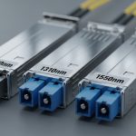
| Wavelength | C-band typically 1530–1565 nm | C-band or vendor-specific DWDM grid | Check datasheet center frequency |
| Reach (typical planning) | Up to tens of km to long-haul depending on model | Metro to long-haul depending on dispersion budget | Verify with vendor link calculator |
| Connector | LC (often) | LC or SC variants by platform | Confirm cage and fiber breakout |
| Optical power (TX) | Vendor-specific launch power class | Vendor-specific launch power class | Compare to switch RX sensitivity |
| Optical RX sensitivity | Vendor-specific sensitivity rating | Vendor-specific sensitivity rating | Included in datasheet tables |
| Management | DOM or equivalent (vendor-defined) | DOM or vendor-defined | Look for I2C page maps in docs |
| Operating temperature | Commercial or industrial grade options | Commercial or industrial grade options | Example: Finisar/FS.com specify ranges per SKU |
Practical tip: if your switch vendor lists supported optics, treat it as a compatibility contract. For example, Cisco optics compatibility guidance and vendor interoperability matrices can be as important as the optical reach itself. Cisco optical compatibility resources
Deployment scenario: metro aggregation without doubling fiber
Imagine a 3-tier network with 48-port 100G top-of-rack switches feeding aggregation routers in a metro ring. You have 12 km of installed fiber between aggregation sites, but the spare fiber count is limited because ducts are already fully utilized. In this scenario, you choose a 100G single lambda transceiver at the aggregation-to-aggregation layer so you can reuse a single wavelength per link and avoid needing parallel “A and B” fibers that would require new construction permits.
Operationally, the rollout goes like this: you pull OTDR traces for worst-case sections, confirm connector loss at each splice, and compute a link budget using vendor sensitivity and launch power. During acceptance testing, you verify that the switch reports clean optics telemetry via DOM (temperature, bias current, received power) and that the link stays within BER targets under normal traffic bursts. If the site is temperature-variable, you also validate that the module remains within its rated operating range and that the transceiver firmware aligns with the host’s optics profile.

Selection criteria checklist engineers actually use
Use this ordered checklist to avoid buying the wrong optics class. It is written for field and procurement workflows, where you need repeatable decisions.
- Distance and fiber quality: measure span length and connector/splice loss; collect OTDR where possible.
- Wavelength plan: confirm center wavelength and grid alignment if using DWDM-style single-lambda optics.
- Link budget inputs: compare TX power, RX sensitivity, and margin for aging and temperature drift.
- Switch compatibility: verify the exact module is supported by your switch model and software version (optics interoperability is not universal).
- DOM and telemetry behavior: ensure your platform reads expected DOM fields and that alarms map correctly.
- Operating temperature: choose commercial vs industrial grade based on ambient conditions; include enclosure airflow assumptions.
- Vendor lock-in and optics governance risk: check if third-party optics are allowed and what happens during RMA or firmware mismatches.
- Power and thermal headroom: confirm the module power draw fits your platform’s thermal design envelope and PSU capacity.
Pro Tip: In metro deployments, many “mystery” link flaps are not optical reach issues—they are marginal dispersion and connector cleanliness problems that only show up under specific traffic patterns. Run a longer soak test while monitoring received power and error counters, not just link-up status.
Common mistakes and how to troubleshoot them fast
Below are frequent failure modes when installing a 100G single lambda transceiver, with root cause and corrective action.
Link does not come up after insertion
Root cause: switch compatibility mismatch (electrical profile, firmware, or optics authentication behavior) or wrong cage type. Some platforms require specific optics IDs or supported transceiver lists.
Solution: check the switch optics compatibility matrix for the exact module part number and firmware; confirm the module is the correct form factor (e.g., QSFP-DD vs CFP2/CFP4 depending on platform). Re-seat and verify DOM is readable; compare module vendor revision to what your switch expects.
Link comes up but BER/errored seconds climb
Root cause: insufficient optical margin due to underestimated connector/splice loss, or dispersion penalties for the installed fiber type. Contamination can also reduce effective coupling efficiency.
Solution: clean connectors using approved procedures and inspect with an optical microscope; re-measure with a certified power meter. Recalculate the link budget with worst-case loss and confirm RX sensitivity and dispersion tolerance against the actual fiber. If you have a DWDM grid, verify wavelength assignment and channel plan.
Telemetry shows high temperature or rising bias current over hours
Root cause: airflow mismatch inside the cage, blocked vents, or the module operating outside its rated temperature range. A host may also throttle or alter power rails under certain conditions.
Solution: confirm ambient and intake temperature at the rack; improve airflow; ensure the module is seated correctly and that blank panels are installed to avoid recirculation. If you need industrial grade, replace with a SKU rated for your environment and re-run the soak test.
Intermittent dropouts during maintenance windows
Root cause: patch panel movement, connector micro-misalignment, or transceiver handling damage (ESD or physical stress on fibers).
Solution: establish a handling SOP: proper ESD straps, gentle fiber bend radius control, and a post-maintenance verification step using error counters and received power telemetry.
Cost and ROI reality: OEM vs third-party optics
Pricing depends heavily on reach class and modulation type. In many enterprise and metro procurement cycles, 100G single lambda transceivers often land in a range that can be several times the price of short-reach 100G optics, but they can still be cost-effective when they remove construction work or reduce downtime risk. OEM modules typically cost more but can simplify acceptance testing and reduce interoperability uncertainty.
For TCO, include: expected failure rate, RMA turnaround time, spare inventory strategy, and the cost of testing labor. Third-party optics may cut unit cost, but you must budget time for compatibility validation and consider whether your vendor will honor support during incidents. If you deploy multiple sites, standardized module governance can prevent “optics sprawl,” which is often the hidden cost driver.
FAQ
What is the main advantage of a 100G single lambda transceiver?
The primary advantage is efficient use of fiber routes by carrying 100G over one wavelength. This can reduce the need for additional parallel fibers and simplify patching in constrained metro environments. The tradeoff is that you must confirm reach and dispersion tolerance with the actual link budget.
How do I verify compatibility with my switch?
Check the switch vendor optics compatibility list for the exact part number and firmware level. Then confirm DOM telemetry is readable and that alarms map correctly to the platform. If you are using third-party optics, plan a controlled validation with your specific software release.
Do I need special cleaning tools for LC connectors?
Yes. Use connector cleaning kits and inspect with an optical microscope before and after insertion, especially when you see high BER. Contamination can mimic “bad reach” and cause intermittent errors.
What telemetry should I monitor during acceptance testing?
Monitor DOM-reported temperature, TX bias current, TX/RX power, and any vendor-specific optical diagnostics. Pair that with Ethernet error counters such as errored seconds and corrected/un-corrected error metrics available on your switch. Run a soak test long enough to capture thermal drift and real traffic patterns.
Can I mix optics vendors in the same network?
In many cases you can, but optical behavior and telemetry mappings vary by vendor. The safest approach is to validate interoperability per switch model and software version, and keep a consistent optics family within a given link type to reduce troubleshooting complexity.
When should I prefer multi-lambda optics instead?
Prefer multi-lambda when you have ample fiber parallelism and need simpler reach assumptions at lower cost. If your biggest constraint is fiber availability or duct capacity, a 100G single lambda transceiver often becomes the practical option, provided the dispersion and channel plan are validated.
For next steps, map your existing fiber spans and patching constraints, then run a link-budget worksheet against the exact module datasheet before you buy. If you want a broader view of optical module types and form factors, see 100G QSFP28 vs CFP2 optics for data center and metro.
Author bio: I work hands-on with field deployments, validating optical links using DOM telemetry, BER counters, and vendor link calculators under real rack airflow and patch-panel conditions. I write from the perspective of engineers who must get links live quickly, then keep them stable through change windows and environmental drift.