In modern racks, optical links do not fail from bits alone; they fail from heat, dust, and marginal airflow. This article helps data center engineers and facilities leads design transceiver thermal cooling into rack planning for 10G, 25G, 100G, and 400G optics, so you can avoid CRC storms, link flaps, and premature module drift. You will get a field-focused top list, a spec comparison table, troubleshooting patterns, and a decision checklist you can apply during installs and refresh cycles.
Top 8 decisions for transceiver thermal cooling that field teams get right

When I plan a leaf-spine cabinet, I treat every transceiver like a small heater perched on a thermally sensitive connector. The goal is not just “cool air somewhere,” but predictable heat removal through the cage, airflow path, and ambient limits defined by the vendor. Below are eight decisions that usually separate stable deployments from recurring optical complaints.
Match optics to the switch cage airflow design
Start with the host switch’s mechanical and thermal assumptions. Many platforms expect a specific front-to-back cooling pattern, with baffles that force air through the port area. If you install optics into a cage that sees reduced velocity because of a missing blank panel, the transceiver temperature can rise even when the room feels “cold.”
In practice, I have seen 25G SFP28 links that passed BER tests on day one degrade after a row reconfiguration removed a blanking panel. The root cause was not fiber or optics; it was throttled airflow in the port zone.
- Best-fit scenario: Leaf-spine ToR or spine switches in high-density racks with strict front-to-back airflow.
- Pros: Improves thermal margin without changing optics.
- Cons: Requires mechanical verification during rack changes.
Verify operating temperature and derating behavior
Optics vendors publish operating temperature ranges and often imply derating indirectly through performance curves. For example, typical “standard” modules might be specified for 0 to 70 C, while extended variants cover -5 to 85 C depending on the product family and laser technology. Your rack ambient and local hot-spot temperature must sit comfortably below the module’s limit after accounting for airflow constraints.
Thermal margin matters because laser bias current and receiver sensitivity both shift with temperature. Even if a link appears up, subtle temperature drift can elevate error rates under certain traffic patterns.
- Best-fit scenario: Cabinets near aisle obstructions, cable hot spots, or with variable fan speeds.
- Pros: Prevents “works on the bench, fails in production” behavior.
- Cons: Extended-range modules can cost more.
Choose connectors and optics that respect the thermal interface
The transceiver thermal cooling path includes the module body, the cage, and the airflow regime around the connector face. Poor cage contact, oxidation, or mechanical misalignment can add thermal resistance and raise the module temperature. Use clean optics, inspect cage latches, and avoid forcing incompatible module types into a cage.
On the electrical side, many pluggables integrate digital diagnostics through I2C (commonly exposed via vendor implementations). Temperature readings should be treated as a control signal, not a decorative metric.
- Best-fit scenario: Field swaps, high churn deployments, or mixed-vendor optics environments.
- Pros: Reduces hot-spot risk at the cage interface.
- Cons: Requires process discipline for cleaning and handling.
Compare reach and wavelength options with thermal and power realities
Not all optics are thermally equal. Higher-speed coherent or long-reach designs may increase power dissipation, and different wavelength bands can correlate with different packaging and thermal behavior. Use a comparison table to align wavelength, reach, connector, and typical power dissipation when you design cooling capacity.
Even if your switch can “electrically” support a given optical type, thermal cooling must match the module’s heat budget. Always check the vendor datasheet for maximum power and the specified case temperature measurement point.
| Optic type (example) | Data rate | Wavelength | Reach | Connector | Typical Tx/Rx power class | Operating temp range |
|---|---|---|---|---|---|---|
| Cisco SFP-10G-SR (example) | 10G | 850 nm | ~300 m over OM3/OM4 (varies by fiber) | LC | Low-to-moderate module power; confirm datasheet | Often 0 to 70 C (confirm exact SKU) |
| Finisar FTLX8571D3BCL (example) | 10G | 850 nm | ~300 m (varies) | LC | Low-to-moderate module power; confirm datasheet | Often 0 to 70 C (confirm exact SKU) |
| FS.com SFP-10GSR-85 (example) | 10G | 850 nm | ~300 m over OM3/OM4 (varies) | LC | Low-to-moderate module power; confirm datasheet | Often 0 to 70 C or extended variants (confirm exact SKU) |
| QSFP28 SR4 (example family) | 100G | ~850 nm (SR4) | ~100 m on OM3/OM4 (varies) | MT-RJ or MPO (device dependent) | Higher module power than 10G; confirm datasheet | Often 0 to 70 C (confirm exact SKU) |
Note: Power dissipation and exact temperature ranges vary by manufacturer and revision. Treat the table as a planning framework, then validate each SKU against its own datasheet.
For standards context, Ethernet optical interfaces follow IEEE 802.3 specifications for electrical/optical behavior, while the thermal management details are governed primarily by vendor mechanical and environmental test methods. See IEEE 802.3 for the link-level requirements; see vendor datasheets for the thermal limits. [Source: IEEE 802.3 series; Source: Cisco SFP module datasheets; Source: Finisar/II-VI optical module datasheets]
- Best-fit scenario: Mixed port speeds and optics in the same rack.
- Pros: Helps size airflow and fan curves correctly.
- Cons: Requires per-SKU verification; no single “rule” fits all optics.
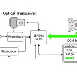
Instrument the rack: treat DOM temperatures as control telemetry
Digital optical monitoring (DOM) provides temperature, laser bias current, transmit power, and receive power. Engineers often check DOM only after alarms, but for thermal cooling you want proactive baselines. During commissioning, log DOM temperature at steady traffic and compare it to the module’s thresholds.
In a real rollout, I set up a 24-hour burn-in window where we pinned traffic at typical peak utilization. We then confirmed that transceiver temperatures stayed below a conservative margin from the module maximum, and that the margin did not collapse when we introduced cable management changes.
Pro Tip: DOM “temperature” is usually measured inside the module case, not the cage or the surrounding air. If you see stable DOM temps but rising CRCs, suspect fiber cleanliness or receiver power drift; if you see DOM temps climb during fan speed changes, suspect airflow bypass from missing blanks or blocked baffles.
- Best-fit scenario: Commissioning, capacity expansions, and fan-fail simulations.
- Pros: Converts thermal cooling from guesswork into measurable control.
- Cons: Requires automation or disciplined manual logging.
Design for airflow bypass and cable-induced turbulence
Air does not follow your intent; it follows the path of least resistance. In dense racks, thick patch cords, sharp bend radii, and poorly managed slack can create turbulence and bypass around the port area. The result is a temperature rise localized to the transceiver row, even while the room average seems safe.
Use blanking panels, route cables to minimize obstruction in the immediate front-to-back lane, and verify that fan modules maintain the intended velocity at the switch front. If your facility uses variable-speed fans, validate thermal behavior under low-speed modes.
- Best-fit scenario: High-density cable plants with frequent re-cabling.
- Pros: Reduces both thermal risk and contamination exposure.
- Cons: Requires physical layout discipline and periodic audits.
Plan power and PDU headroom alongside thermal cooling
Thermal cooling is coupled to power delivery. Higher-speed optics and active components draw more power, and in some switch designs the module power and onboard ASIC loads change together with operating mode. When you under-size PDU capacity or ignore power distribution efficiency, you can induce thermal stress indirectly through higher internal temperatures.
In a consolidation project, we hit an unexpected fan ramp because the switch backplane load increased after a software upgrade. The optics themselves were nominal, but the system reached a new thermal operating point. The fix was not only airflow; we rebalanced power distribution and reduced oversubscription.
- Best-fit scenario: Upgrades that change utilization, port mix, or line card population.
- Pros: Prevents cascading thermal effects from power oversubscription.
- Cons: Needs coordinated electrical and mechanical planning.
Choose OEM vs third-party optics with thermal and compatibility safeguards
Thermal cooling performance depends on packaging quality and how well a module conforms to the host’s cage expectations. OEM optics often receive more validation against a specific switch model, while third-party optics may vary in DOM behavior, thermal characteristics, or firmware compatibility. Many enterprises accept third-party optics for cost control, but you must implement compatibility and temperature validation.
For example, third-party 10G SR optics such as FS.com variants can be viable, but validate that the switch accepts them, that DOM temperature values behave within expected ranges, and that optics remain stable under your thermal envelope. Check vendor notes on interoperability and DOM implementation quirks.
- Best-fit scenario: Budget pressure with a controlled qualification process.
- Pros: Potentially lower module cost and faster procurement.
- Cons: Higher qualification effort; possible vendor lock-in via compatibility checks.
Common mistakes and troubleshooting moves for transceiver thermal cooling
Missing blank panels causing airflow bypass
Root cause: Gaps around the switch front allow air to short-circuit around the port area. Transceivers run hotter than expected, even though room temperature looks acceptable.
Solution: Install correct blanks, confirm baffle integrity, and measure the delta between ambient and module DOM temperature during steady traffic.
Mixing optics families without validating temperature and DOM thresholds
Root cause: A module may be electrically compatible but thermally different, or it may report temperature differently. The result is unexpected thermal margin erosion and rising errors under load.
Solution: Validate each SKU against the switch vendor’s compatibility guidance and run a burn-in test that monitors DOM temperature, bias current, and link error counters.
Using unclean fiber or dirty MPO/LC connectors while chasing “thermal” symptoms
Root cause: Engineers sometimes interpret link flaps as temperature issues. But dirty connectors can cause receive power degradation and CRC growth that correlates with traffic patterns, making it look like a cooling problem.
Solution: Clean and inspect connectors with proper tools, then verify receive power and error counters before altering thermal design.
Obstructing airflow with cable bundles too close to the port face
Root cause: Cable bundles and sharp bends create turbulence and reduce local airflow velocity across cages.
Solution: Re-route cables with separation from the airflow lane, use structured cable management, and re-check module temperatures after the change.
Cost and ROI note: what thermal cooling changes really cost
In many deployments, the highest ROI actions are not new chillers; they are rack-level mechanical fixes: blank panels, better cable management, and airflow validation. OEM optics often cost more than third-party modules; as a rough planning range, 10G SR optics may sit in the tens to low hundreds of dollars per module, while 100G QSFP28 optics can be several times higher depending on reach and vendor. Your TCO also includes qualification labor, spare inventory, and the operational cost of troubleshooting link instability.
Extended-temperature modules can reduce failure risk in marginal thermal environments, but they increase upfront cost. The ROI equation becomes favorable when you quantify downtime, truck rolls, and the cost of maintaining stable BER under peak fan-speed variability.
For thermal design, the cheapest “cooling” is usually the airflow path you already have—made honest by baffles and verified by telemetry.
Selection criteria checklist: engineer the thermal margin before you buy
- Distance and link budget: Confirm reach requirements for your fiber type and connector loss; do not use a longer-reach optic unless you need it.
- Switch compatibility: Check vendor compatibility lists and the host’s transceiver support policy.
- DOM support and telemetry behavior: Ensure the switch reads temperature and power metrics consistently for your module family.
- Operating temperature and max case limits: Match rack hot-spot conditions to the module’s specified operating range.
- Operating power dissipation: Use datasheets to plan airflow and avoid hidden heat load increases.
- Operating environment: Consider dust control, variable fan modes, and proximity to heat sources on the same airflow lane.
- Vendor lock-in risk: Balance OEM validation with third-party cost savings via a structured qualification process.
- Maintenance and spares: Plan for cleaning tools, spare optics, and a repeatable swap workflow.
Summary ranking table: best first moves for transceiver thermal cooling
| Rank | Top decision item | Primary risk reduced | Typical effort | Impact |
|---|---|---|---|---|
| 1 | Match optics to switch cage airflow design | Local hot spots from bypass airflow | Low to medium | High |
| 2 | Verify operating temperature and derating behavior | Thermal margin erosion over time | Medium | High |
| 3 | Instrument the rack with DOM telemetry | Blind troubleshooting and late detection | Medium | High |
| 4 | Design for airflow bypass and cable turbulence | Hot spots caused by obstruction | Medium | Medium to high |
| 5 | Choose connectors and optics that respect thermal interface | Thermal resistance at cage contact | Low | Medium |
| 6 | Plan power and PDU headroom alongside cooling | Thermal coupling from power oversubscription | Medium | Medium |
| 7 | Compare reach and wavelength options with thermal realities | Hidden heat load from wrong optic class | Medium | Medium |
| 8 | Choose OEM vs third-party with qualification safeguards | Compatibility quirks and thermal variance | High | Medium |
FAQ
How do I tell if transceiver thermal cooling is the real problem?
Compare module DOM temperature trends against ambient and fan mode changes. If DOM temperature rises while error counters also climb under steady traffic, suspect thermal cooling; then verify airflow bypass, baffle integrity, and cage contact.
Do all optics measure temperature the same way?
No. DOM temperature is a module internal measurement and may not match external cage temperature. Treat thresholds as vendor-specific and validate with burn-in on the exact switch model.
Is it better to buy extended-temperature optics or improve rack airflow?
Improve airflow first when you can, because it benefits every module and reduces other risks like dust accumulation. Extended-temperature optics are a strong mitigation when mechanical constraints limit airflow or when hot-spot variability is unavoidable.
Can third-party transceivers cause thermal cooling issues?
They can, if packaging, thermal design, or DOM behavior differs from OEM expectations. The safe approach is a qualification process: verify switch compatibility, monitor DOM temperature and bias current, and run traffic burn-in under expected ambient conditions.
What troubleshooting step should come before touching cooling settings?
Inspect and clean the fiber connectors and verify receive power and error counters. Thermal cooling problems often correlate with time and fan changes, but dirty connectors can mimic symptoms through traffic-dependent receive degradation.
Where should I start if I inherit a rack with frequent link flaps?
Start with airflow bypass checks: confirm blanks, baffles, and cable routing around the switch front-to-back lane. Then baseline DOM telemetry during normal and reduced fan-speed modes before swapping optics.
If you want the next layer of practical guidance, review transceiver diagnostics DOM for how to use temperature, bias current, and power readings to build a thermal cooling playbook. Until then, treat thermal margin as a design requirement, not a hope.
Author bio: I am a data center engineer who designs rack layouts, validates airflow paths, and troubleshoots optical reliability using DOM telemetry and switch optics compatibility checks. My work spans power distribution, PDU capacity planning, and field deployment of 10G to 400G transceivers in real production cabinets.