In modern leaf-spine and campus networks, a “mystery” link flap is often traced back to transceiver thermal cooling problems rather than fiber loss or optics alignment. This article helps network engineers, data center field techs, and procurement leads evaluate thermal management approaches for high-speed optical modules before outages happen. You will get a practical Top 8 items framework, a decision checklist, troubleshooting pitfalls, and a selection table grounded in real module and switch constraints.
Top 1: Match the transceiver to the switch thermal envelope
Thermal performance starts with mechanical and airflow compatibility, not with heatsinks alone. Many pluggable optics (SFP, SFP+, QSFP+, QSFP28, OSFP, CFP2) rely on a defined airflow path through the switch cage; if your rack airflow is reversed or blocked, the module’s internal thermistor can sit above safe operating limits. Always verify the vendor’s specified operating temperature range and the switch vendor’s supported module list, because thermal cooling requirements are often implicit in the platform design.
Key specs to check: module case temperature limits, typical power draw (e.g., around 1.0 W to 3.5 W depending on data rate and interface), and the switch’s airflow rate requirements. For example, Cisco and Arista platforms frequently assume front-to-back cooling with specific fan RPM targets; if you run with reduced fan speed, the transceiver thermal cooling margin shrinks.
Best-fit scenario: You are deploying mixed optics across a 48-port ToR switch model and want consistent link behavior during peak load and summer ambient spikes. Use the vendor “optics compatibility” matrix and confirm that the optics’ DOM temperature readings stay comfortably below the upper threshold.
- Pros: Reduces unplanned downtime; prevents “works in lab, fails in field” behavior.
- Cons: Limits part choices; may increase BOM cost if you must use OEM-supported optics.
Top 2: Use DOM temperature telemetry to enforce cooling policy
Digital Optical Monitoring (DOM) provides per-module telemetry such as laser bias current, received power, transmit power, and module temperature. Engineers can operationalize this data by setting alert thresholds and correlating thermal excursions with interface errors, CRC counts, and link renegotiations. A robust transceiver thermal cooling process treats temperature as a first-class SRE signal, not just a diagnostic field.
Operational details field teams use: poll DOM every 30 to 60 seconds, log min/avg/max temperature per module, and compare against the vendor absolute maximum. Many optical modules implement the I2C-based management interface defined by industry practice (often aligned with SFF specifications); the switch reads those registers and can surface them in telemetry systems like InfluxDB/Grafana or vendor-native monitoring.
Pro Tip: In practice, temperature “spikes” that last under 2 minutes can still trigger laser bias derating or temporary receiver sensitivity changes. So alert on rate of change (dT/dt) or short-window maxima, not only on a long-term average.
- Pros: Early warning; enables objective cooling tuning after rack changes.
- Cons: DOM polling adds telemetry load; thresholds must be tuned per platform.
Top 3: Design airflow paths that actually cool the cage, not just the room
Room temperature is an unreliable proxy for module temperature because transceiver thermal cooling depends on local airflow velocity at the front of the optics and heat dissipation through the chassis. Hot spots often arise from blocked intake grilles, mis-seated blanks, or cable bundles that obstruct the air channel between fan modules and the pluggable bay. In thermal failure investigations, the root cause frequently sits in the micro-environment around the transceiver, not in the server rack’s average ambient.
Concrete deployment guidance: verify front-to-back airflow for the switch, ensure that unused ports have approved airflow blanks, and keep the cable bend radius from intruding into the transceiver airflow lane. In one real-world scenario, a team tracked intermittent 10G link drops to a partially blocked intake filter; after clearing the obstruction and restoring fan duty cycle, DOM temperature max fell by 8 to 12 C and interface errors dropped to baseline.
- Pros: Often the lowest-cost fix; improves reliability across all modules.
- Cons: Requires disciplined rack hygiene and change control.
Top 4: Choose optics with realistic power and thermal resistance targets
Even with perfect airflow, high power density can reduce thermal margin. Thermal resistance is frequently represented as junction-to-ambient and depends on the module packaging, heatsink contact, and air velocity. For transceiver thermal cooling, you should compare optics by their stated power and understand how higher power correlates with higher equilibrium temperature under the same airflow.
Practical comparison examples: 10G SR optics (e.g., Cisco SFP-10G-SR, Finisar FTLX8571D3BCL, FS.com SFP-10GSR-85) typically draw around ~1 W to ~1.5 W depending on design and generation. Higher-rate modules like 25G/50G/100G variants can run materially higher, though exact values vary by vendor and whether the design uses advanced DSP and cooling structures.
| Transceiver type | Typical wavelength | Typical reach | Typical data rate | Typical optical TX power | Typical module power | Connector | Operating temp range |
|---|---|---|---|---|---|---|---|
| SFP-10G-SR class | 850 nm | Up to 300 m (OM3/OM4 varies) | 10G | Varies by vendor | ~1.0 to ~1.5 W | LC | 0 to 70 C (varies by module) |
| SFP28-25G SR class | 850 nm | Up to ~100 m (OM4 typical) | 25G | Varies by vendor | ~1.8 to ~3.0 W (varies) | LC | 0 to 70 C (varies) |
| QSFP28-100G SR4 class | 850 nm | Up to ~100 m (OM4 typical) | 100G | Varies by vendor | ~3.5 to ~6.0 W (varies) | LC (MPO-LC depending on design) | 0 to 70 C (varies) |
Best-fit scenario: You are upgrading from 10G to 25G/50G and expect higher per-port power. You need to estimate thermal margin changes before the rollout, especially in densely packed shelves with constrained airflow.
- Pros: Better thermal headroom planning; fewer surprises during peak operation.
- Cons: Requires vendor datasheets; power numbers can differ by revision.
Top 5: Validate heatsink contact and module insertion consistency
Thermal transfer depends on mechanical interfaces: the module’s metal shell, the switch cage contact points, and any internal thermal pads or spring pressure. Poor insertion (partially latched optics), debris on the cage, or repeated hot swapping can reduce contact quality. In those cases, transceiver thermal cooling fails even though the room airflow is correct.
Field validation steps: reseat modules fully, inspect for bent pins or misaligned latch geometry, and clean dust from the cage vents using approved procedures. For high-density systems, verify that optic latches are fully engaged across all ports after maintenance windows.
- Pros: Fast remediation; often resolves intermittent thermal alarms.
- Cons: Requires disciplined maintenance tooling and ESD-safe practices.
Top 6: Prefer optics with validated thermal design and documented derating behavior
Some transceivers implement laser driver derating or internal thermal throttling; others simply risk violating absolute maximum temperature. The difference matters for link stability: under thermal stress, a module may reduce output power, increasing error rates before a hard failure. Look for vendor documentation that describes temperature-induced behavior and any derating curves, not only the operating range.
Standards context: While IEEE 802.3 defines electrical and optical interfaces at the system level, module thermal behavior is governed by the module’s own design and vendor datasheets. Still, the operational limits you choose should align with the platform’s supported optics and the transceiver’s specified absolute maximum temperature.
- Pros: Predictable behavior during thermal stress; fewer “silent degradations.”
- Cons: Not all third-party vendors publish derating details.
Top 7: Manage connector and fiber cleanliness to avoid thermal side effects
At first glance, fiber cleanliness seems unrelated to transceiver thermal cooling. But dirty connectors can increase optical attenuation, forcing the receiver to operate closer to sensitivity limits and potentially driving higher bias/thermal stress modes depending on the module design. In practice, teams see temperature alarms correlate with rising RX power degradation after patch panel work.
Best-fit scenario: You are running high utilization and performing frequent moves, adds, and changes (MACs) in an MPO-LC dense patch environment. Thermal stability improves when you also enforce connector cleaning discipline, inspection using microscopes, and standardized dust caps.
- Pros: Improves signal integrity and reduces thermal stress indirectly.
- Cons: Requires process maturity and inspection tooling.
Top 8: Build a procurement and maintenance plan that reduces thermal failure risk
Thermal cooling is not only a design problem; it is a lifecycle risk management issue. Procurement decisions should account for operating temperature ratings, DOM support, compatibility with your switch platform, and expected failure modes. Maintenance plans should specify inspection cadence, reseating procedures, and airflow verification after rack moves or filter replacements.
Cost & ROI note: OEM optics can cost roughly 20% to 80% more than third-party equivalents, but they often provide tighter compatibility validation and faster RMAs. If a single optics-related outage costs a team several hours of incident response plus potential customer impact, the ROI of buying optics with known thermal behavior and switch support can be positive even when unit prices are higher. TCO also includes labor for reseating, cleaning, and troubleshooting, which rises sharply when module thermal cooling is not predictable.
- Pros: Lower probability of thermal incidents; smoother upgrades.
- Cons: More upfront diligence and vendor documentation review.
Summary comparison: thermal cooling drivers that matter most
Engineers typically see the biggest impact from combining airflow correctness, module power/thermal resistance, and DOM-driven enforcement. The table below ranks practical levers by influence and operational effort.
| Lever | What it changes | Typical impact on module temperature | Operational effort | Best for |
|---|---|---|---|---|
| Airflow path validation | Local air velocity and heat removal | High (often 5 to 15 C swings) | Medium | Rack hygiene and incident prevention |
| DOM temperature monitoring | Early detection and alerting | Medium (prevents escalation) | Low | SRE and NOC operations |
| Optics power selection | Equilibrium temperature under load | Medium to High (power scales heat) | Low to Medium | Upgrades and capacity planning |
| Heatsink/contact integrity | Thermal contact resistance | Medium (reseating can fix) | Low | Post-maintenance anomalies |
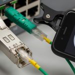
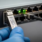
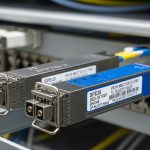
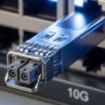
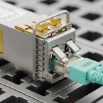
Image note: Use this kind of close-up photography during audits to verify latch seating and visible airflow obstruction causes.
Selection criteria / decision checklist for transceiver thermal cooling
- Distance and optics class: confirm wavelength and reach for your fiber type (OM3/OM4/OS2) and split ratios.
- Switch compatibility: use the platform vendor optics list and confirm mechanical fit and airflow assumptions.
- Thermal envelope: verify module operating temperature range and confirm it stays below the switch’s validated limits under peak ambient.
- DOM support: ensure the switch can read temperature and power metrics; plan alert thresholds tied to thermal events.
- Operating temperature and derating behavior: prefer optics with documented thermal derating curves and predictable output changes.
- Operating power and thermal resistance proxies: compare module power draw and understand power scaling with data rate.
- Connector cleanliness process impact: reduce optical attenuation-driven stress; enforce inspection and cleaning.
- Vendor lock-in risk: balance OEM validation against third-party availability; require compatibility testing in a staging rack.
Common mistakes / troubleshooting tips
Thermal cooling issues can masquerade as optical problems. Use the following failure modes to accelerate root cause analysis.
-
Mistake 1: Blaming fiber loss when temperature is the real trigger.
Root cause: airflow obstruction or heatsink contact loss increases module temperature, leading to reduced transmitter output or increased receiver errors. RX power may drift while the underlying thermal cause remains.
Solution: correlate DOM temperature max with interface error bursts (CRC/FEC counters if available) and check airflow lane obstructions before cleaning fibers.
-
Mistake 2: Using third-party optics without verifying DOM telemetry behavior.
Root cause: some optics may expose temperature but not map thresholds or fields as expected by the switch. Monitoring becomes misleading, delaying detection of thermal excursions.
Solution: stage-test in a controlled rack, confirm the switch reads temperature registers correctly, and validate alert triggers by inducing controlled airflow changes.
-
Mistake 3: Assuming room ambient temperature guarantees safe module temperature.
Root cause: local airflow velocity and direction dominate module temperature. A rack with correct room ambient can still starve the transceiver cage due to blocked intake filters or cable routing.
Solution: measure per-rack fan performance and validate front-to-back flow; use thermal camera scans around the pluggable bay during peak load.
-
Mistake 4: Partial insertion after maintenance.
Root cause: a module that is not fully latched can have worse thermal contact and unstable optical alignment, causing intermittent link drops.
Solution: reseat optics with full latch engagement, inspect the cage for debris, and recheck DOM temperature and link state stability.
Image note: This vector illustration is useful for training new field technicians on airflow obstruction patterns.
FAQ
How do I tell if transceiver thermal cooling is actually failing?
Look at per-module DOM temperature telemetry and correlate it with interface errors or link resets. If temperature max approaches the vendor’s upper operating limit during peak load, and reseating or airflow corrections improve stability, thermal cooling is the likely cause.
Do I need OEM optics for thermal performance, or can third-party work?
Third-party optics can work reliably, but you must validate compatibility with your switch platform and confirm DOM telemetry and alert behavior. In staging tests, track module temperature distribution under your expected airflow and ambient conditions.
What temperature thresholds should I alert on?
Start with vendor datasheet guidance and your platform validated limits, then set early warning alerts below those limits. Practically, many teams alert on temperature approaching the upper operating bound and on short-window maxima rather than only long-term averages.
Can dirty fiber connectors cause thermal issues?
They can contribute indirectly by increasing optical attenuation and pushing the receiver/transmitter closer to sensitivity or bias targets. Clean connectors usually improve link quality and can reduce stress-related drift, but you should confirm causality using DOM temperature correlation.
What is the fastest troubleshooting workflow for suspected thermal cooling?
First, check DOM temperature max and its timing relative to errors. Second, verify airflow direction, confirm blanks are installed, and inspect for blocked intake or failed fans. Third, reseat the module and clean the cage contact area if allowed by your maintenance policy.
Where can I find authoritative interface and optics guidance?
IEEE 802.3 provides the interface definitions for Ethernet over fiber, while vendor datasheets define module power, temperature ranges, and DOM behavior. For platform-specific requirements, rely on the switch vendor optics compatibility guidance and installation manuals.
Sources: [Source: IEEE 802.3] [Source: Cisco SFP and QSFP documentation] [Source: Vendor transceiver datasheets for SFP-10GSR class and QSFP28 SR4 class modules] [Source: SFF pluggable interface guidance as referenced by module manufacturers].
[[EXT:https://standards.ieee.org/standard/]] IEEE 802.3 standards portal
[[EXT:https://www.cisco.com/]] Cisco optics and platform documentation
[[EXT:https://www.finisar.com/]] Finisar optics datasheets and product guidance
[[EXT:https://www.fs.com/]] FS.com optics product pages and datasheets
Next step: run a staging validation that combines airflow verification, DOM-based thermal alerts, and a reseat/inspection procedure for your exact switch and optics part numbers using transceiver monitoring and DOM telemetry as your operational baseline.
Author bio: I have deployed high-density 10G to 100G optical fabrics in production data centers, using DOM telemetry, thermal camera scans, and rack airflow audits to stop recurring transceiver thermal cooling incidents. I write implementation-focused guidance for field engineers and platform teams based on vendor datasheets and real incident postmortems.