You are probably maintaining a mixed fleet of switches, optics, and cabling where “it should work” often fails due to timing, DOM behavior, or power budget limits. This article tracks the SFP form factor evolution from 1G-era deployments to modern high-speed variants, then turns that history into a field-ready selection workflow. It helps network engineers, data center operations teams, and procurement leads who need predictable optics interoperability, not vendor folklore.
Top 8 items in the SFP form factor evolution journey

Below is a top-N listicle that maps what changed in the transceiver ecosystem as data rates climbed, while the physical SFP shell stayed familiar. Each item includes key electrical/optical facts, best-fit scenarios, and pragmatic pros/cons so you can make decisions during spares planning or live troubleshooting.
SFP at 1G: LC fiber and “just enough” link margins
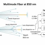
In the earliest SFP deployments, the dominant payload was Gigabit Ethernet at 1.25 Gbps line rate using 1000BASE-SX (multi-mode) or 1000BASE-LX (single-mode). Engineers learned quickly that link stability was less about the optics alone and more about connector cleanliness, patch cord length, and modal dispersion in OM2/OM3 fiber. The SFP mechanical interface made hot-swapping easy, but optical budget discipline still mattered.
Key specs that shaped operations
- Wavelengths: typical SX around 850 nm, LX around 1310 nm
- Connector: common LC duplex for fiber; RJ-45 for copper variants
- Control plane: basic ID via I2C in the SFP specification; DOM was not consistently used
- Temperature: standard commercial and extended industrial bins existed, but many networks standardized on one
Best-fit scenario
Legacy access and aggregation tiers using 1G ToR uplinks, where cabling is already proven and the goal is predictable optics replacement. In practice, teams keep a small spares pool of known-good part numbers to avoid surprise behavior with non-default EEPROM fields.
Pros: Mature compatibility, wide vendor availability, stable interoperability.
Cons: Limited reach at higher loss budgets, and older multi-mode assumptions can break when fiber is re-patched.
10G SFP+: the form factor stays, optics become budget-critical
As 10G arrived, the SFP shell evolved into SFP+ electrically (higher-speed SerDes and different host expectations). The “same-looking module” problem became real: some hosts accept SFP+ only when specific firmware and vendor transceiver lists align. Optical budget moved from “it usually works” to measured engineering: insertion loss, splice loss, and worst-case receiver sensitivity under temperature drift.
Key specs and what changed
- Data rate: 10.3125 Gbps line rate for 10G Ethernet
- Common optics: 850 nm MMF (SR), 1310 nm SMF (LR)
- Typical reach (rule-of-thumb): SR often planned around a few hundred meters to ~300 m on OM3 with proper launch; LR often around 10 km on single-mode
- DOM: became increasingly common to support alarms and proactive maintenance
Best-fit scenario
A 3-tier data center leaf-spine design where access switches uplink to aggregation at 10G and you standardize on SR over OM3/OM4. Teams typically record link loss per path during acceptance testing and store it alongside module part numbers for rapid rollback.
Pros: Strong ecosystem, DOM support improves operational visibility.
Cons: SR performance depends heavily on fiber type, patch cord quality, and cleaning discipline.
25G SFP28: tighter tolerances and better optics density
At 25G, the optics landscape shifted toward smaller timing margins, higher integrated photonics, and more aggressive power management. SFP28 became the practical stepping stone for enterprise and mid-market data centers that needed faster uplinks without the cost and port-density trade-offs of larger form factors. Engineers also began treating DOM telemetry as a first-class input to operational dashboards.
Key specs
- Data rate: 25.78125 Gbps line rate
- Wavelength: SR at ~850 nm for MMF; ER at ~1310 nm for SMF
- Reach planning: SR frequently targeted around ~70 m on OM3 and higher on OM4/OM5 depending on module class and launch conditions
- Interoperability: more sensitive to host PHY/firmware behavior than in 1G/10G eras
Best-fit scenario
Enterprise core refresh where you replace 10G uplinks with 25G while keeping the same fiber infrastructure. A common operational approach is to run optics burn-in in a staging rack at ambient extremes and verify DOM thresholds match the host’s expectations.
Pros: Good port density and predictable performance when fiber is validated.
Cons: Compatibility issues increase: wrong module generation or firmware can cause link flaps.
40G/100G era: SFP form factor evolution leaves SFP behind for higher speeds
When networks pushed to 40G and 100G, the industry largely moved to QSFP families (QSFP+ and QSFP28) because lane counts and electrical bandwidth requirements outgrew what SFP-style pinouts and power envelopes handled comfortably. This is a key point in the SFP form factor evolution story: the physical “SFP look” was no longer the best match for the scaling path.
What engineers observed
- Lane scaling: higher aggregate rates require more parallel lanes or higher-speed lanes
- Power and thermal: higher-speed transmitters and multi-channel optics increase heat density
- Host compatibility: QSFP ports often enforce stricter vendor or compliance requirements
Best-fit scenario
Core-to-core or spine uplinks where you must hit 100G per link and can justify QSFP-based optics and transceiver budget. Teams plan for higher airflow and monitor module temperature via DOM.
Pros: Mature support for 40G/100G with robust reach options.
Cons: Not “drop-in” if you expected SFP-style reuse across generations.
200G/400G and coherent optics: where “SFP” becomes a planning conversation
At 200G and beyond, networks increasingly adopted architectures that balance optics cost, dispersion tolerance, and power draw. While the SFP footprint is no longer the dominant choice for these speeds, the operational discipline from SFP-era deployments still matters: DOM telemetry, link budget accounting, and connector hygiene. In many environments, the “SFP form factor evolution” lesson becomes governance: standardize optics verification, store calibration notes, and treat optics as part of the configuration management system.
Key facts for decision-makers
- Coherent vs direct-detect: coherent typically supports longer reach and higher efficiency per bit at distance, but adds complexity
- Fiber impairments: polarization mode dispersion and chromatic dispersion become relevant at longer reaches
- Operational tooling: transceiver telemetry and optical diagnostics are essential for fast root-cause analysis
Best-fit scenario
Metro and regional links where you need long reach and can justify coherent optics and specialized transceiver management. Teams often use automated link validation workflows and strict patch cord control to reduce variable loss.
Pros: Better scalability for large aggregate throughput.
Cons: More complex troubleshooting than short-reach direct-detect.
800G in practice: form factor fragmentation and strict compliance
When you reach 800G, the industry uses multiple module families and electrical interfaces; the “SFP-style” convenience is not the primary driver. Instead, you must manage compliance with host platform requirements, power/thermal constraints, and optics performance under real temperature and aging conditions. This is where SFP-era operational habits pay off: measure, document, automate diagnostics.
Real-world engineering constraints
- Thermal: module temperature and airflow become first-order constraints; monitor DOM temperature and host fan profiles
- Electrical budgets: host PHY settings and equalization can determine whether a module trains successfully
- Interoperability: “any compatible optic” is rarely safe at this scale without compliance testing
Best-fit scenario
High-density AI training floors with spine-leaf fabrics where 800G uplinks are common. Teams typically pre-qualify optics with the exact switch model and firmware release, then lock transceiver part numbers for the change window.
Pros: Enables massive throughput per rack row.
Cons: Higher qualification effort; tighter compatibility gates.
Pro Tip: In mixed-generation networks, the fastest root-cause pattern is to compare DOM lane temperature, bias current, and received power across known-good vs suspect optics, not just link up/down LEDs. At 25G and above, subtle receiver margin issues can look like “firmware incompatibility” even when the module is physically seated correctly.
Selection criteria: the engineer’s checklist for SFP form factor evolution
Use this ordered checklist to avoid expensive trial-and-error. It is designed for operations teams managing optics spares, and for buyers who must reduce vendor lock-in risk without breaking compliance.
- Distance and fiber type: confirm OM3/OM4/OM5 vs single-mode; validate patch cord and splice loss with acceptance test results
- Switch compatibility: verify the exact transceiver family and host firmware release notes; confirm whether the host enforces vendor IDs
- DOM support and telemetry mapping: ensure the module provides standard diagnostic fields and that monitoring tooling can ingest them
- Operating temperature: match commercial vs extended industrial bins to your rack ambient and airflow profile
- Electrical and power budget: check host power per port and module power class; confirm thermal design margins
- DOM and alarm thresholds: align your alerting thresholds to expected bias drift and RX power ranges
- Vendor lock-in risk: evaluate third-party compliance programs, return policies, and your ability to qualify alternate optics quickly
- Standards alignment: prefer modules that clearly state compliance to relevant IEEE and vendor datasheet requirements
Reference anchors: IEEE 802.3 for Ethernet physical layer expectations, and vendor datasheets for DOM behavior and optical specs. anchor-text: IEEE 802.3 standard
Comparison table: practical spec differences you must account for
This table compares common “SFP-era” speeds and typical optics characteristics that drive link budget and compatibility. Exact reach depends on module class, fiber type, and host equalization settings.
| Module / speed class | Typical wavelength | Typical reach target | Connector | DOM / diagnostics | Operating temperature range | Notes for selection |
|---|---|---|---|---|---|---|
| SFP 1G SX / LX | 850 nm / 1310 nm | ~550 m (SX, OM2 typical) to ~10 km (LX, SM) | LC duplex (fiber) | Often limited in older deployments | Commercial and extended bins vary by vendor | Validate fiber type and cleanliness; older MM assumptions can fail after re-patching |
| SFP+ 10G SR / LR | 850 nm / 1310 nm | ~300 m (SR on OM3 typical planning) / ~10 km (LR) | LC duplex (fiber) | Common; monitor bias and RX power | Typically commercial and industrial options | Budget insertion and splice loss; SR is sensitive to launch conditions |
| SFP28 25G SR / ER | ~850 nm / ~1310 nm | ~70 m (SR on OM3 planning) / higher on OM4; ER varies | LC duplex (fiber) | Common; telemetry improves troubleshooting | Commercial or industrial | Host firmware and equalization can affect link training stability |
| QSFP28 (for 100G class, not SFP) | 850 nm / 1310 nm | Multi-mode short reach or single-mode long reach | Varies (often MPO) | Common | Varies | Plan for higher thermal density and stricter compatibility testing |
| 800G module families (not SFP) | Depends on direct-detect or coherent approach | Varies widely | Varies | Usually extensive diagnostics | Varies; airflow critical | Pre-qualification with exact switch model and firmware is mandatory |
For concrete examples of commonly deployed optics, engineers often reference vendor and third-party datasheets such as Finisar and FS.com module families. anchor-text: Finisar optical products anchor-text: FS.com transceivers
Common mistakes / troubleshooting in SFP form factor evolution
Even experienced teams get burned when they assume optics are interchangeable across generations. Here are concrete failure modes that map directly to the SFP form factor evolution timeline.
Connector contamination blamed on “bad optics”
Root cause: Dirty LC endfaces introduce excess insertion loss and can push the receiver below sensitivity, especially at 25G+ where margins tighten. Solution: Inspect with a fiber scope, clean with lint-free wipes and approved cleaner, then re-test with a known-good patch cord. Track cleaning events as part of change control.
Host compatibility mismatch after a firmware upgrade
Root cause: Switch firmware can change transceiver authentication behavior, PHY equalization settings, or DOM parsing. A module that worked before may fail link training or show intermittent flaps. Solution: After firmware changes, validate optics with the exact supported transceiver list and record DOM fields during link bring-up.
Wrong fiber type assumptions during reuse
Root cause: Teams reuse patch panels assuming OM3 performance, but field repairs may swap in OM2 or older cables with different attenuation and modal bandwidth. Solution: Verify fiber type by documentation and OTDR traces, then re-run link budget calculations using measured worst-case loss.
Thermal starvation in high-density racks
Root cause: As you move to higher-speed modules (and later 800G-class ecosystems), heat density rises. Fans set for older ports may not provide adequate airflow, causing DOM temperature alarms and gradual degradation. Solution: Confirm airflow paths, set fan profiles appropriate to the new module class, and alert on rising module temperature trends.
FAQ about SFP form factor evolution in real networks
What does “SFP form factor evolution” mean operationally?
It means the physical shell stayed recognizable, but electrical interfaces, optics classes, and host compatibility expectations changed as speeds increased. Practically, you must treat each generation (SFP, SFP+, SFP28) as a new compatibility and margin regime, not as a simple replacement.
Can I use third-party optics across SFP, SFP+, and SFP28?
Often yes, but you must validate against the specific switch model and firmware. Third-party optics can differ in DOM implementation details and timing characteristics that affect link training at higher speeds.
How do I verify compatibility before ordering spares?
Check the switch vendor transceiver compatibility list and then run a staged acceptance test in a lab rack using the same firmware. During