When your rack is already full and your cooling budget is tight, optics upgrades become an engineering problem, not a shopping task. This article explains how SFP form factor evolution from 1G to 800G affects distance, power, fiber mapping, and switch compatibility. It helps data center operators, network engineers, and field techs plan migrations from legacy SFP to newer pluggables without surprise downtime.
Prerequisites: what you must measure before swapping optics
Before you touch a single transceiver, capture the physical and electrical constraints that drive SFP form factor evolution decisions. Most failures I see in the field come from ignoring temperature, DOM behavior, or link budget assumptions. You will also need the exact switch part numbers and optics qualification guidance from the vendor.
- Verify switch model and port type (example: Cisco Nexus/ Catalyst variants, Arista EOS, Juniper QFX). Record whether ports support SFP, SFP+, SFP28, or vendor-specific cages.
- Collect fiber plant data: fiber type (OM3/OM4/OS2), strand count, polarity method (MPO vs LC), and measured end-to-end loss using an OTDR or calibrated light meter.
- Confirm power and cooling envelope for the rack and row. Record inlet temperature and typical airflow pattern; high-density optics can raise module and PCB temperatures.
- Plan management expectations: DOM/EEPROM support, thresholds, and alerting integration (SNMP/telemetry).
Expected outcome: A migration plan that matches ports, fiber, and thermal headroom so the optics you select actually link up on first deployment.
Step-by-step implementation: mapping 1G to 800G across pluggable generations
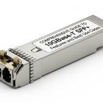
The core idea behind SFP form factor evolution is that the mechanical envelope stayed recognizable, while optics, electronics, and interfaces advanced. In practice, you will treat each generation as a distinct capability set: 1G SFP, 10G SFP+, 25G SFP28, and higher-speed small form factor options that may still use “SFP-like” mechanics but different signaling and power classes.
Classify your current links by speed and reach
Pull interface counters and transceiver inventory from the switch. Identify which links are truly constrained by optics reach versus those constrained by oversubscription or congestion. For example, a 1G SFP uplink at 550m multimode might be replaced by a 10G SFP+ at 300m, while a long-haul OS2 link may need different optics entirely.
Expected outcome: A spreadsheet of source port, destination device, speed target, and fiber type.
Translate speed targets into wavelength and link budget requirements
Use IEEE 802.3 specifications and vendor datasheets to confirm wavelength and reach. For SR optics, you will typically see 850 nm class multimode behavior; for LR/ER style links, you will see 1310 nm or 1550 nm single-mode. Then validate against your measured fiber loss and connector penalties.
Expected outcome: A shortlist of optics families that meet link budget with margin for aging and patch panel variability.
Compare key module specs that change across generations
Even when the form factor looks similar, electrical power, temperature behavior, and connector types can differ. Below is a practical comparison engineers use during procurement and rack planning.
| Module family (examples) | Typical data rate | Wavelength | Reach class (typical) | Connector | Avg module power | Operating temp |
|---|---|---|---|---|---|---|
| SFP (legacy) | 1G | 850 nm or 1310 nm | ~550 m MM or ~10-40 km SM | LC | ~0.8–1.5 W | 0 to 70 C (typical) |
| SFP+ (common 10G) | 10G | 850 nm / 1310 nm | ~300 m MM or ~10 km SM | LC | ~1.5–2.5 W | 0 to 70 C (typical) |
| SFP28 (25G) | 25G | 850 nm / 1310 nm | ~100 m MM to ~10 km SM | LC | ~2.5–3.5 W | -5 to 70 C (typical) |
| High-speed small pluggables (approaching 800G systems) | Lane-based aggregation | Varies by design | Depends on optics architecture | Often MPO/MTP at system level | Higher per-system budget | -5 to 70 C (typical) |
Expected outcome: A spec-aligned selection that matches your fiber and your rack thermal limits.
Validate DOM and switch compatibility before bulk install
DOM support is not uniform across vendors and generations. Some switches enforce optic vendor qualification; others rely on standard SFF-8472/related diagnostics. Plan a pilot: insert one module per optics family, confirm link up, check diagnostics, and verify telemetry thresholds.
Expected outcome: Reduced risk of “module present but link down” events during rollout.
Account for power draw and airflow at scale
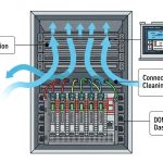
In high-density ToR and leaf-spine deployments, optics power turns into a thermal load. As you move from 10G to 25G and beyond, module power can increase and airflow requirements tighten, especially near exhaust zones. Measure inlet and outlet temperatures after installing a representative number of modules.
Expected outcome: Thermal compliance without throttling or intermittent link errors.
Pro Tip: In many failures, the optics themselves are fine; the issue is fiber polarity or patch panel mapping. During SFP form factor evolution migrations, engineers often reuse cabling labels from older LC-based links, but modern runs can introduce different polarity expectations or different transceiver pinouts at the system level. Confirm polarity end-to-end with a known-good reference light test before blaming the module.
Cost and ROI: what changes when you move through SFP form factor evolution
OEM optics often cost more but provide the smoothest compatibility path for qualified switch platforms. Third-party optics can reduce purchase price, but you must account for qualification risk, potential support friction, and higher failure rates in out-of-spec thermal conditions. As a rough field reality, enterprise 10G SFP+ SR modules may land in the mid tens of dollars per unit, while newer 25G optics often cost more; system-level 800G rollouts typically shift cost into optics aggregation architectures and higher port density.
Expected outcome: A TCO view that includes qualification effort, spares strategy, and cooling impact rather than only unit price.
Selection criteria checklist engineers actually use
- Distance and reach class: use measured loss plus connector/coupler penalties, not only vendor “max distance.”
- Wavelength and fiber type: SR 850 nm vs LR 1310 nm vs ER 1550 nm; MM vs SM must match the plant.
- Switch compatibility and vendor qualification: confirm supported part numbers and any “approved optics” lists.
- DOM/telemetry behavior: ensure thresholds and alerting work with your monitoring stack.
- Operating temperature and thermal budget: confirm the module spec and validate rack airflow after installation.
- Lock-in risk: decide whether to standardize on OEM for critical paths or use third-party with a controlled pilot.
- Connector and polarity handling: LC vs MPO/MTP at the system level; verify patching method.
Common mistakes and troubleshooting: top failure modes
Below are the field issues that most often derail SFP form factor evolution projects. Each includes the root cause and a practical fix.
-
Mistake: Module swaps that “look correct” but never link up.
Root cause: Fiber polarity reversal, wrong patch mapping, or mismatched connector type at the patch panel.
Fix: Verify polarity using a light test; re-patch according to the transceiver pair mapping (especially when moving between generations or system architectures). -
Mistake: Link flaps under load or after a few hours.
Root cause: Thermal stress from insufficient airflow or placement near hot exhaust.
Fix: Measure inlet/outlet temps and module diagnostics; adjust baffles/airflow, reseat modules, or move to a cooler row. -
Mistake: “Module not supported” or DOM alarms.
Root cause: Switch qualification rules, incompatible DOM implementation, or incorrect optic type for the port.
Fix: Check platform optics compatibility documentation; test one unit per vendor; enable/verify DOM monitoring settings. -
Mistake: Reach shortfall despite “spec match.”
Root cause: Underestimated patch panel loss