When a data center outgrows 25G optics faster than it can pull new fiber, a QSFP28 QSFP56 upgrade migration becomes a practical question: can you reuse the existing patching, fiber plant, and switch port breakout strategy? This article helps network and field engineers plan an upgrade path that minimizes downtime and keeps optics qualification realistic. You will find engineering specs, a selection checklist, and troubleshooting patterns seen during rollouts.
Why QSFP28 QSFP56 upgrade migration works with existing fiber
At a high level, both QSFP28 and QSFP56 modules are short-reach pluggables that operate over multimode or single-mode fiber, often using similar wavelength families and link budgets set by IEEE 802.3 specifications. The key migration lever is that you can frequently keep the same physical fiber routes and patch panel organization while changing the transceiver type. In practice, teams map each current 25G lane plan to the new 50G or 100G lane aggregation behavior, then validate that the switch supports the target module in the intended port mode.
Most “reuse the infrastructure” projects succeed when three conditions align: (1) the fiber plant already supports the required reach and modal bandwidth for the wavelength plan, (2) the optics are compatible with the switch’s electrical front-end and firmware port settings, and (3) the deployment uses a controlled optics qualification process. Vendors often provide a compatibility matrix; ignoring it is the fastest route to intermittent link failures.
What stays the same
Typically unchanged elements include the MPO/MTP patching layout (same rack-to-row paths), labeling scheme, and fiber management practices. If your current design uses OM4 or OM5 multimode, your measured end-to-end loss and connector quality often remain valid for the upgraded transceivers, provided the new link budget does not exceed the margin you have after cleaning and re-termination.
What changes
What changes is the electrical lane mapping and module operational mode. A field engineer will usually verify whether the switch expects breakout (for example, 1x100G to 4x25G) or uses native 100G/200G framing, then confirm the optics use the correct speed grade and coding. In many rollouts, the biggest “surprise” is not fiber loss; it is port bifurcation settings and optics DOM behavior.
Specs that decide whether you can migrate safely
The fastest way to reduce risk is to compare target module families by wavelength, reach class, connector type, and power/thermal constraints. Below is a practical comparison template you can use during procurement and lab validation.
| Parameter | Example QSFP28 SR (25G) | Example QSFP56 SR (50G) | Engineering implication |
|---|---|---|---|
| Data rate | Up to 25.78125 Gb/s per lane | Up to 50 Gb/s per lane (varies by vendor) | Port mode and lane mapping must match switch settings |
| Wavelength (multimode) | ~850 nm (typical SR) | ~850 nm (typical SR) | Often compatible with existing OM4/OM5, but verify link budget |
| Reach class | Commonly 100 m (OM4) | Commonly ~150 m (OM4/OM5 varies) | Measured loss matters; do not rely on label-only fiber types |
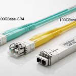
| Connector | MPO-12 (typical QSFP28 SR) | MPO-16 or vendor-specific (QSFP56 SR variants) | Patch panel adapters or new cassettes may be required |
| DOM | Usually supported (I2C, vendor DOM) | Usually supported (I2C, vendor DOM) | DOM compatibility can affect threshold alarms |
| Operating temp | Typically 0 to 70 C for commercial | Typically 0 to 70 C for commercial; check range | Hot aisles and constrained airflow can trigger thermal throttling |
| Typical power | Often ~2 to 4 W (varies) | Often ~4 to 6 W (varies) | Confirm cooling capacity when density increases |
For concrete examples, teams frequently validate optics such as Cisco SFP-10G-SR for older generations, then move to higher-speed families like Finisar or OEM equivalents for 25G/50G. When selecting QSFP56 SR modules, check specific part numbers and datasheets from the optics vendor and the switch OEM compatibility list. [Source: IEEE 802.3 (relevant Ethernet PHY clauses for 25G/50G/100G class links)] [Source: Vendor transceiver datasheets and switch optics compatibility guides]
Pro Tip: In many QSFP28 QSFP56 upgrade migrations, the “link down” root cause is actually a mismatched MPO adapter path, not transceiver optics. If your QSFP56 SR uses a different MPO polarity or connector count than your QSFP28 SR, you can see intermittent BER spikes even when loss numbers look fine. Validate polarity end-to-end and confirm jumper mapping before blaming the module.
Deployment scenario: reusing patch panels in a leaf-spine upgrade
Consider a 3-tier data center leaf-spine topology with 48-port 10G or 25G ToR switches feeding a spine layer. The leaf layer currently runs 25G server uplinks using QSFP28 SR over OM4, with each leaf using 4 uplinks at 100G equivalent capacity. The team plans a phase upgrade to boost spine-to-leaf throughput by moving to QSFP56 SR optics on the spine side, while keeping the same rack-to-row fiber routes and patch panel organization.
In a field schedule, they perform this in two windows: first, they install QSFP56 modules in the spine ports and update switch port mode settings (including speed and any required bifurcation). Second, they replace leaf-side optics module type only where the switch requires it. Before the cutover, they run an OTDR or certified end-to-end loss test and confirm connector cleanliness; during cutover, they monitor link state and optical diagnostics (DOM thresholds, Tx bias, and temperature) for several hours.
Selection criteria checklist for QSFP28 QSFP56 upgrade migration
Use this ordered checklist to reduce surprises during a QSFP28 QSFP56 upgrade migration:
- Distance and fiber class: verify the measured end-to-end loss budget and ensure the fiber type (OM4 vs OM5) supports the wavelength and reach target.
- Switch compatibility: confirm the exact switch model supports QSFP56 modules in the required port mode; consult the OEM optics matrix.
- Connector and patching impact: confirm QSFP56 SR connector format (often MPO variant) and plan any adapters or cassette changes.
- DOM and monitoring: validate that DOM fields and alarm thresholds behave correctly in your network management stack.
- Operating temperature and airflow: estimate power and thermal load at higher optical density; confirm cold aisle/hot aisle airflow paths.
- Vendor lock-in risk: compare OEM-only optics versus third-party availability, and check warranty and RMA policies.
- Qualification plan: run a lab test with representative modules and patch cords, then do a staged field rollout.
Common pitfalls and troubleshooting tips
Pitfall 1: Port mode mismatch after optics swap. Root cause is incorrect speed setting, breakout mode, or firmware configuration. Solution: confirm switch configuration matches the module’s intended operating mode, then reload optics profiles if the platform supports it.
Pitfall 2: Polarity or jumper mapping error on MPO-based links. Root cause is reversed MPO polarity or mismatched adapter orientation when moving from QSFP28 MPO-12 layouts to QSFP56 MPO variants. Solution: use polarity verification tools or documented polarity mapping, then re-terminate or re-seat jumpers and re-test BER and optical power levels.
Pitfall 3: Assuming fiber labels equal fiber performance. Root cause is connector contamination, aging, or unexpected patch cord loss. Solution: clean connectors with validated procedures, then measure with certified methods; if margins are tight, rework patch cords or reduce link length.
Pitfall 4: Thermal throttling or marginal optics under hot-aisle conditions. Root cause is insufficient airflow after adding higher-power modules. Solution: measure transceiver temperature via DOM, improve airflow, and ensure fan profiles match the new density.
Cost and ROI note: what you can realistically expect
Pricing varies widely by vendor, speed grade, and whether you buy OEM-branded optics. In many enterprise and mid-market data centers, optics often land in the rough range of $150 to $600 per transceiver for short-reach pluggables, with higher-speed or branded variants at the top end. ROI comes from avoiding new fiber pulls and reducing downtime; however, TCO must include qualification labor, spare inventory, and potential warranty friction between OEM and third-party optics.
From a field perspective, the “hidden cost” is time spent in troubleshooting when compatibility matrices are ignored. If third-party optics are used, plan for a longer acceptance window and keep at least one known-good OEM module per platform model for rapid swaps.
FAQ
Can I reuse the same patch panels when upgrading from QSFP28 to QSFP56?
Often yes, but not always. The fiber routes and patch panel locations can remain unchanged, yet QSFP56 SR optics may use a different MPO connector format or polarity mapping, requiring adapter cassettes or jumper changes. Validate connector type and polarity before scheduling cutover. [Source: Vendor transceiver datasheets]
Will OM4 multimode usually be sufficient for QSFP56 SR?
It depends on measured link loss, connector quality, and the specific module’s reach specification. If your current QSFP28 SR links already operate near the limit, you may have less margin after upgrading. Always use certified loss measurements and confirm the new link budget requirements. [Source: IEEE 802.3 and vendor link budget documentation]