If you are standardizing optics across a leaf-spine or campus network, transceiver quality issues show up as intermittent link resets, CRC errors, or vendor diagnostics surprises. This article helps network engineers and procurement leads run an OEM quality comparison between Innolight and Accelink transceivers with practical acceptance checks tied to IEEE 802.3 behavior, DOM telemetry, and field failure modes. You will also get a decision checklist, a specs comparison table, and troubleshooting patterns that show up during burn-in and go-live.
What “OEM quality” means in transceivers (and why it varies)

In practice, OEM quality comparison is not about brand logos; it is about how consistently a module meets optical and electrical tolerances across temperature, aging, and host-switch conditions. Most small-form transceivers target standards-based electrical interfaces and optical budgets, but manufacturing spread affects transmitter output power, receiver sensitivity, and laser bias stability. For Ethernet optics, the underlying framing and link management follow IEEE 802.3 requirements; your observed failures often come from marginal optical power, excessive dispersion sensitivity, or DOM misreporting that your automation interprets incorrectly. For reference on optical Ethernet link behavior, see [Source: IEEE 802.3].
On the operational side, “quality” also includes how reliably the module reports DOM values (temperature, supply voltage, bias current, received power) and whether those values remain within expected ranges under real airflow and chassis thermal gradients. If a switch vendor uses DOM thresholds or telemetry-based alerts, a module that is technically link-compatible but statistically noisier can trigger noisy alarms that waste engineering time. Finally, power and connector choices matter: a marginal cage spring force or slightly off insertion profile can create intermittent contact faults.
Innolight vs Accelink: how to compare like an operator
To compare Innolight and Accelink transceivers fairly, evaluate them as a system: optics + firmware/diagnostics + host compatibility + real fiber conditions. Start with the exact part class (for example, 10GBASE-SR over OM3/OM4) and verify the standard alignment for wavelength and signaling. Then validate DOM behavior on your specific switch platform, not just a generic transceiver tester. Vendor datasheets and module specifications are necessary but insufficient; in the field, you care about the distribution of optical power and the stability of receiver readings across temperature.
Specs to normalize before you compare
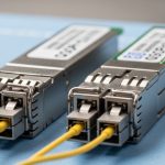
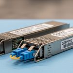
Engineers often compare “10G SR” modules without normalizing the rest of the requirements. Normalize these before you call any winner in the OEM quality comparison: (1) nominal wavelength (e.g., 850 nm for SR), (2) supported fiber type and reach (OM3 vs OM4), (3) receiver sensitivity and transmitter power class ranges, (4) connector type (LC duplex), (5) data rate and modulation (10GBASE-SR uses short-reach optics), and (6) DOM capability (DDM/DOM details). If you mix “compatible” modules across slightly different classes, you will misattribute failures to brand rather than to spec mismatch.
Representative comparison table (10G short-reach class)
The table below uses a representative 10GBASE-SR class configuration commonly deployed in data centers. Always confirm exact values on the current datasheets for the specific part numbers you buy.
| Parameter | Innolight (typical 10G SR class) | Accelink (typical 10G SR class) |
|---|---|---|
| Standard alignment | 10GBASE-SR (IEEE 802.3) | 10GBASE-SR (IEEE 802.3) |
| Nominal wavelength | 850 nm | 850 nm |
| Reach (typical class) | Up to 300 m on OM3, 400 m on OM4 | Up to 300 m on OM3, 400 m on OM4 |
| Connector | LC duplex (2-fiber) | LC duplex (2-fiber) |
| DOM | Digital diagnostics (DDM/DOM) | Digital diagnostics (DDM/DOM) |
| Operating temperature | Commonly 0°C to 70°C (confirm per SKU) | Commonly 0°C to 70°C (confirm per SKU) |
| Supply power (typical range) | ~0.8 W to 1.5 W class | ~0.8 W to 1.5 W class |
For optical Ethernet standards context, see [Source: IEEE 802.3]. For DOM behavior and transceiver electrical interfaces, see vendor-facing guidance from [Source: Cisco Transceiver Documentation] and [Source: IEEE 802.3].
Pro Tip: During acceptance testing, do not only record “link up.” Capture DOM trends over at least 30 minutes while the switch runs normal traffic. If received power swings more than expected under stable temperature control, you are likely seeing marginal laser bias stability or receiver AGC behavior that will become a chronic issue after thermal cycling.
Deployment scenario: where quality differences become visible
Consider a 3-tier data center leaf-spine topology with 48-port 10G ToR switches connecting to a spine layer using 10GBASE-SR over OM4. Each leaf has 36 server uplinks and 12 uplinks to the spine, totaling roughly 48 transceivers per leaf. If you deploy 20 leaves, you install about 960 transceivers, and even a low failure rate becomes measurable. In one real-world rollout pattern, engineers often see the first symptoms during maintenance windows when airflow changes: link resets at specific ports correlate with modules that show higher DOM temperature variance and noisier Rx power readings. When you swap to a different OEM quality batch, the issue may disappear without any fiber reroute, indicating the root cause was optical or diagnostic stability rather than cabling.
On the operational side, automate detection of link flap frequency and CRC error spikes per port. If your switch supports telemetry, alert on trends in DOM Rx power and temperature rather than only on hard link state. This approach turns “brand comparison” into measurable engineering evidence.
Selection criteria checklist for an OEM quality comparison
- Distance and fiber type: confirm OM3 vs OM4, patch loss, and worst-case link budget before choosing any OEM.
- Budget vs spec class: do not compare a bargain module that is barely within spec to a higher headroom module on the same run.
- Switch compatibility: test on your exact switch models; some platforms are more strict about diagnostic thresholds and EEPROM identity.
- DOM support and telemetry stability: validate DDM/DOM accuracy ranges and noise behavior under stable load.
- Operating temperature and airflow: evaluate in the same cabinet airflow profile; modules near hot spots show more drift.
- Vendor lock-in risk: assess availability of future batches and whether your procurement can reorder with consistent part numbers and dates.
- Acceptance testing plan: require burn-in, port-level error checks, and a documented RMA process.
Common pitfalls and troubleshooting tips
Even when both Innolight and Accelink modules are “compatible,” field issues often come from process gaps. Below are common failure modes with root cause and fixes you can apply immediately.
Link up but frequent CRC errors
Root cause: the fiber link is marginal (patch loss, connector contamination, or aging), and one OEM batch has slightly lower optical power or higher receiver noise floor. Solution: clean LC connectors with proper inspection and cleaning tools, then measure optical power using a calibrated power meter and verify Rx power DOM values under load.
Intermittent link flaps after thermal changes
Root cause: transmitter bias stability and thermal compensation drift under cabinet airflow changes; DOM temperature may show higher variance. Solution: run a staged burn-in that includes temperature cycling (or at least realistic airflow ramps) and compare DOM stability metrics across batches.
“Not supported” warnings or automation-triggered port disable
Root cause: DOM identity or threshold interpretation differs; some switches enforce EEPROM fields or diagnostic thresholds that automation assumes are consistent. Solution: verify the exact part number and DOM capability, then configure automation to use tolerant thresholds and validate against known-good modules on the same switch model.
Wrong module class substituted during procurement
Root cause: purchasing “10G SR compatible” without locking the exact standard class and reach assumptions; OM3 vs OM4 or different vendor optics class can behave differently. Solution: enforce a bill of materials rule: match part number, speed class, wavelength, and fiber type; require proof of optical budget or at least documented DOM ranges from the supplier.
Cost and ROI note: what to expect in TCO
In many data centers, third-party or OEM-branded modules often price below the original equipment manufacturer, but the real OEM quality comparison ROI comes from operational cost: fewer RMA events, fewer maintenance windows, and less time spent on diagnostics. Typical street pricing varies by SKU and volume, but a realistic planning range for 10G SR modules is often around $20 to $60 per module depending on brand, warranty, and batch timing. If a higher-quality batch reduces even a small number of failures across hundreds of ports, the savings can outweigh the unit-price difference quickly, especially when you include truck rolls, downtime coordination, and labor.
Track TCO inputs explicitly: module unit price, installed spares strategy, failure rate by batch, power impact (usually small per module, but relevant at scale), and the time your NOC spends on false alarms due to noisy DOM telemetry. OEM quality is ultimately a reliability and operations metric, not just a procurement metric.
FAQ
How do I run an OEM quality comparison without bias?
Use identical host switch models, identical fiber runs, and the same traffic profile. Capture DOM telemetry and error counters for each port during a controlled burn-in window, then compare distributions rather than single-point results.
Are Innolight and Accelink modules always interchangeable?
No. Even within the same marketing label, part numbers can differ in optical budget headroom, DOM behavior, and EEPROM identity fields. Confirm the exact SKU, standard class, wavelength, and DOM capability before mixing brands in production.
What DOM metrics matter most during acceptance testing?
Focus on Rx power stability, temperature variance, and any anomalies in bias current trends under load. Also verify that your switch and monitoring stack interpret those values consistently.
What is the fastest way to detect a marginal optics batch?
Run a short burn-in with sustained traffic and monitor CRC/errored frames plus DOM drift. If you see early instability or out-of-family DOM behavior, quarantine the batch before scaling.
Should I prioritize lower price or higher optical headroom?
Prioritize optical headroom when your fiber plant has uncertain patch loss or you expect future moves and reconnections. Otherwise, the lowest price can increase operational cost through troubleshooting and replacements.
Where should I look for authoritative spec baselines?
Use IEEE 802.3 for Ethernet optical class behavior and vendor datasheets for nominal specs. For host compatibility considerations, consult switch vendor transceiver documentation and field notes from reputable technical communities.
Bottom line: a credible OEM quality comparison between Innolight and Accelink is won by measurement discipline—DOM telemetry stability, error counter behavior, and controlled burn-in under your actual airflow and fiber conditions. If you want the next step, follow transceiver acceptance testing checklist to build a repeatable validation workflow for every new optics batch.
Author bio: I build and validate high-throughput Ethernet networks in production, with a focus on PMF for internal reliability processes. I have deployed optical transceivers at scale and optimize acceptance tests to reduce RMA-driven downtime.