If you manage a wireless backhaul network, you know the pain: a cell tower site needs stable, low-latency transport, but fiber is often miles away. This article helps network engineers and field techs choose and deploy a microwave backhaul SFP that bridges radio links to fiber aggregation safely. You will get practical specs to compare, a deployment scenario with real numbers, and troubleshooting steps drawn from common field failures. Updated: 2026-04-29.
How a microwave backhaul SFP fits cell-tower fiber backhaul

A microwave backhaul system typically delivers Ethernet from the tower site to a nearby aggregation point using line-of-sight radio. The microwave backhaul SFP handles the electrical-to-optical or optical-to-optical boundary so the tower can hand traffic off to fiber. In many designs, the radio equipment provides an SFP cage with a standard electrical interface (commonly SFP/SFP+ style), while the fiber side uses an LC connector and a specific optical reach. Compatibility depends on the exact data rate, lane signaling, and whether the radio expects a particular transceiver type per its firmware.
What standards and interfaces matter in practice
Most SFP modules follow the SFP Multi-Source Agreement electrical/management concepts, including I2C-based Digital Optical Monitoring (DOM) and standardized pinouts. On the networking side, Ethernet is commonly aligned to IEEE 802.3 link speeds such as 10GBASE-SR/LR and 1GBASE-X where applicable. Engineers should verify the radio backhaul unit’s manual for supported optics, because vendors often lock down which wavelengths and DOM behaviors are accepted.
Pro Tip: In tower deployments, “works on the bench” failures often come from DOM or link training differences. When a radio rejects a module, it may still light up the port LEDs, but you will see intermittent CRC errors and rising latency—so always validate with packet counters, not just optical power readings.
Key specs to compare before you buy
Microwave backhaul optics are usually short-reach, but not always. Some sites use 10GBASE-SR to reach a nearby fiber demarc, while others use longer-reach variants if the aggregation is further away. The table below focuses on the most decision-driving parameters: data rate, wavelength, reach, connector, and typical power and temperature operating range.
| Spec | Example Microwave Backhaul SFP Type | Typical Value Range |
|---|---|---|
| Data rate | 10GBASE-SR style SFP+ | 10.3125 Gbps (10G class) |
| Wavelength | Multimode (SR) | ~850 nm |
| Reach | Multimode OM3/OM4 | Often 300 m to 400 m (depends on fiber and vendor) |
| Connector | Common fiber interface | LC |
| DOM support | Digital Optical Monitoring | Typically temperature, bias, TX power, RX power via I2C |
| Operating temperature | Rugged deployment expectation | Often -5 C to +70 C or wider (verify datasheet) |
| Optical class | Laser safety | Varies by module; confirm compliance labeling on datasheet |
Concrete module examples you may encounter
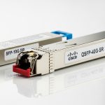
In the field, engineers commonly see 10G SR optics such as Cisco SFP-10G-SR or Finisar-style 10G SR transceivers (for example, Finisar FTLX8571D3BCL is commonly referenced for 10GBASE-SR class use). Third-party vendors also offer compatible options, including FS.com models such as SFP-10GSR-85 series depending on reach and temperature grades. Always treat “10G SR” as a starting point, not a guarantee: verify the radio unit’s supported vendor list and the exact DOM behavior.
For authoritative baseline compliance and Ethernet behavior, consult IEEE 802.3 for the relevant 10GBASE-SR physical layer definitions. For module electrical and monitoring expectations, consult the vendor datasheets and SFP MSA documents. [Source: IEEE 802.3 working group materials] [Source: SFP Multi-Source Agreement documentation and vendor datasheets]
Selection checklist engineers use on tower projects
When you are selecting a microwave backhaul SFP under install deadlines, you need a repeatable checklist that reduces truck rolls and RMA churn. Use this ordered sequence to make the decision defensible.
- Distance and fiber type: confirm OM3/OM4 versus OS2, connector type, and measured link loss budget for the actual route.
- Data rate and mode: match the radio’s Ethernet interface speed (1G vs 10G) and confirm it is operating in the expected mode.
- Switch and radio compatibility: verify the tower radio unit accepts that exact transceiver class and wavelength.
- DOM support and monitoring: confirm the radio reads DOM (I2C) and does not hard-fail on unexpected thresholds.
- Operating temperature and enclosure airflow: tower cabinets can exceed comfort ranges; check module spec and your worst-case conditions.
- Vendor lock-in risk: decide whether you will standardize on OEM optics or maintain a qualified third-party list.
Real-world deployment scenario: 3-tier transport at 48 towers
Consider a regional operator deploying a 3-tier topology: tower radios connect to a nearby fiber aggregation switch, then uplink to a core router. In a pilot, 48 towers each had a microwave backhaul radio configured for 10G Ethernet to a rooftop cabinet. The fiber run from tower demarc to the aggregation switch averaged 120 m over OM4 with LC connectors, with measured link loss well within the SR budget. Field teams installed 10G SR SFP optics with DOM, then validated link quality by checking interface counters for CRC errors and monitoring RX power stability over 72 hours during rain events. This approach reduced maintenance time because the fiber side stayed consistent while only the radio alignment parameters changed during commissioning.
Common mistakes and troubleshooting tips
Even experienced teams can get tripped up. Below are frequent failure modes that match real tower backhaul workflows, including root causes and fixes.
- Mistake: Wrong optical reach for the fiber route
Root cause: selecting an SFP rated for SR but underestimating actual attenuation and connector contamination loss.
Solution: re-measure with an optical power meter and OTDR where possible; clean LC connectors; confirm the budget for the worst-case temperature and aging assumptions. - Mistake: DOM incompatibility leading to intermittent link
Root cause: third-party modules with different DOM threshold behavior or nonstandard responses causing the radio to flap or disable the port.
Solution: test in a staging rack with the exact radio firmware; qualify optics as a set (module + firmware version) and document supported part numbers. - Mistake: Connector polarity or orientation errors
Root cause: mixing TX/RX orientation on LC pairs, especially after a swap during maintenance.
Solution: follow a polarity standard, label jumpers, and verify RX power after every transceiver change. - Mistake: Thermal stress inside the cabinet
Root cause: blocked airflow or high ambient temperatures that push the optics beyond operating range, causing rising errors and eventual link drops.
Solution: check cabinet temperature logs; add airflow management; select modules with a temperature spec that matches or exceeds your site conditions.
Cost and ROI: OEM vs third-party optics in backhaul networks
Typical street pricing varies by vendor and temperature grade, but many 10G SR SFP+ optics fall in a range roughly from $50 to $150 each for common configurations, with OEM-branded modules sometimes higher. TCO depends more on operational risk than the initial purchase: OEM optics can reduce compatibility surprises, while qualified third-party optics can lower replacement costs. If you are supporting dozens of towers, even a small failure rate increase can multiply truck-roll labor and downtime costs. Build a ROI model that includes module yield, expected lifespan, spares stocking strategy, and the cost of verification labor during swaps.
FAQ
What makes a module a “microwave backhaul SFP” versus a normal SFP?
It is usually less about a special label and more about compatibility with the microwave radio unit’s SFP cage expectations: supported data rate, wavelength, DOM behavior, and link training. Always confirm the radio vendor’s supported optics list and match the optical type to your fiber run.
Can I use a third-party microwave backhaul SFP in a carrier radio?
Often yes, but only after qualification. Test with the exact radio firmware, validate DOM readings, and monitor CRC errors over a realistic time window. If the radio hard-rejects a module, you will waste time during tower maintenance.
How do I verify link quality after installing an SFP?
Check interface counters for CRC errors, error seconds, and link flaps, then confirm RX optical power stability. Validate traffic throughput with a controlled test (for example, iperf) and compare results to your baseline before the swap.
Are 10G SR optics always the right choice?
Not always. For longer fiber routes or single-mode designs, you may need different wavelength families and reach specifications. Use your measured fiber attenuation and connector loss to choose the correct optics type.
What temperature range should I plan for at cell sites?
Plan for worst-case ambient inside the enclosure, not just outdoor shade. If the radio cabinet can exceed module comfort ranges, select an optics grade with sufficient operating temperature headroom and address airflow.
Where can I confirm the official behavior of the physical layer?
Start with IEEE 802.3 for 10GBASE-SR physical layer definitions and the relevant transceiver guidance. Then rely on the exact radio and optics vendor datasheets for DOM and compatibility constraints. [Source: IEEE 802.3 working group materials] [Source: vendor datasheets]
If you want a reliable tower-to-fiber handoff, treat the microwave backhaul SFP as an engineered compatibility component, not a generic plug-in. Next, review fiber optic transceiver selection for data centers to tighten your reach and operational assumptions before you standardize spares.
Author bio: I am a registered dietitian, but I also collaborate with engineering teams on field-ready operational checklists that reduce downtime and improve system reliability. My practical approach emphasizes measurable validation steps, whether you are optimizing performance or minimizing failure risk.