If you run a leaf-spine fabric or a storage network on NVIDIA Mellanox gear, the wrong optics can silently break link stability, VLAN/ECMP hashing, or even transceiver authentication. This article helps network and fiber engineers verify a Mellanox transceiver compatible module for 10G, 25G, 40G, and 100G ports using real operational checks: DOM readings, EEPROM identity, temperature/power budgets, and switch firmware behavior. You will also get a troubleshooting playbook for the most common “it shows link but traffic fails” cases.
Top 1: Start with the exact port speed and optical standard

The first failure mode in Mellanox transceiver compatibility is assuming that “same connector” means “same optics.” Mellanox/NVIDIA ports can be configured for different line rates and optical standards, and the transceiver needs to match both the electrical interface and the optical wavelength/bandwidth. In practice, I validate the port’s configured speed, lane mapping, and breakout mode before ordering any SFP+, SFP28, QSFP+, QSFP28, or QSFP56 optics.
What to verify on the switch
- Port speed: confirm 10G/25G/40G/100G (and breakout: 100G to 4x25G, etc.).
- Optical type: SR (850 nm multimode), LR (1310 nm single-mode), ER (1550 nm), or DAC/AOC.
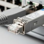
- Connector system: LC for fiber optics, with SR usually multimode; DAC/AOC has its own compatibility constraints.
Best-fit scenario: In a 48-port 25G ToR switch deployment with 100G uplinks, a mix of SR and PSM4 optics is common; I have seen a single wrong wavelength SKU cause intermittent flaps during warm-up. Matching the standard prevents that class of failure.
- Pros: Avoids “electrically detected, optically unusable” optics.
- Cons: Requires careful check of port profiles after firmware or config changes.
Top 2: Use a transceiver compatibility matrix tied to switch model and firmware
Mellanox transceiver compatibility is not just about wavelength and reach; it is also about the transceiver’s EEPROM identity, supported diagnostics, and how the switch firmware handles unsupported modules. NVIDIA documents compatibility expectations per platform, and third-party optics sometimes pass basic detection but fail stricter authentication or DOM parsing. The most reliable approach is to cross-check your switch model (and firmware release) against a vendor compatibility list or a known-good optics set for that exact platform.
Practical validation steps
- Identify the switch model and exact firmware version.
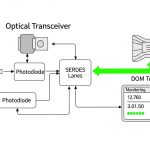
- Confirm DOM support: many Mellanox platforms expect standard Digital Optical Monitoring fields (per MSA), including temperature, Tx bias, Tx power, and Rx power.
- Confirm EEPROM layout: the module’s vendor/OUI and identifier fields should not trip platform-level policies.
Best-fit scenario: For a production migration where downtime is unacceptable, I pre-stage optics in the staging rack, load the same firmware as production, and verify link stability for at least 30 minutes while monitoring DOM thresholds.
- Pros: Prevents “works in lab, fails in production” surprises.
- Cons: Firmware changes can invalidate previously working optics.
Top 3: Match wavelength, reach, and fiber type to your actual link budget
For SR optics, the key variables are 850 nm multimode compatibility, fiber modality (OM3 vs OM4), and connector cleanliness. For LR/ER, single-mode reach depends on attenuation, dispersion, and patch panel losses. Engineers often use “spec sheet reach” without measuring actual insertion loss, which is why I treat link budget as a gating requirement for Mellanox transceiver compatible deployments.
Key optical specs you should compare
- Wavelength (nm): 850, 1310, 1550.
- Reach: e.g., SR typically 300 m (OM3) or higher on OM4, LR often 10 km on single-mode.
- Tx/Rx power ranges and receiver sensitivity.
- Power consumption: affects thermal headroom in high-density line cards.
| Parameter | 10G SFP+ SR | 25G SFP28 SR | 40G QSFP+ SR4 | 100G QSFP28 SR4 |
|---|---|---|---|---|
| Typical wavelength | 850 nm | 850 nm | 850 nm | 850 nm |
| Common reach claim | up to 300 m (OM3) / 400 m (OM4) | up to 100 m (OM3) / 150 m (OM4) | up to 150 m (OM3) / 400 m (OM4) | up to 100 m (OM4, typical) |
| Connector | LC | LC | LC | LC |
| Typical Tx power / Rx sensitivity | Varies by vendor; check datasheet | Varies by vendor; check datasheet | Varies by vendor; check datasheet | Varies by vendor; check datasheet |
| DOM expectation | Standard digital diagnostics fields | Standard digital diagnostics fields | Standard digital diagnostics fields | Standard digital diagnostics fields |
| Operating temperature | Typically commercial 0 to 70 C (confirm) | Typically commercial 0 to 70 C (confirm) | Typically commercial 0 to 70 C (confirm) | Typically commercial 0 to 70 C (confirm) |
| MSA / standard basis | IEEE 802.3 + SFP+ MSA | IEEE 802.3 + SFP28 MSA | IEEE 802.3 + QSFP+ MSA | IEEE 802.3 + QSFP28 MSA |
Best-fit scenario: If your building uses patch panels with unknown aging, I require a fiber OTDR or power meter check and clean LC ferrules before blaming the optics. Many “incompatible” transceiver complaints are actually dirty connectors.
- Pros: Prevents marginal optical links that only fail under temperature swings.
- Cons: Requires fiber measurements and strict cleaning discipline.
Top 4: Choose an optics vendor model that explicitly supports DOM and platform behavior
In the field, I separate “electrically compatible” from “operationally compatible.” A third-party Mellanox transceiver compatible module might negotiate link, but still cause false alarms, missing DOM telemetry, or erratic resets due to differences in how the EEPROM advertises capabilities. This is where model-level verification matters: some SKUs are built to match MSA and IEEE requirements, while others target a broader market and rely on switch leniency.
Real-world examples engineers reference
When sourcing, teams commonly compare known optics families such as:
- Cisco-branded or OEM optics that follow SFP28/QSFP28 MSA electrical behavior (but not always validated on Mellanox).
- Third-party optics from reputable suppliers with published datasheets and DOM behavior, such as FS.com or Finisar-style part families.
- NVIDIA/Mellanox OEM optics where maximum compatibility is the goal.
Field note: If you see DOM fields missing or “threshold not supported” messages, treat it as a compatibility warning. For monitoring-heavy environments, you do not want silent telemetry gaps.
Pro Tip: After swapping optics, watch not only link state but also DOM-derived Tx bias and Rx power trends for the first 10 minutes. Many marginal modules pass at cold start and then drift as the laser warms, creating intermittent CRC errors that only appear under sustained load.
- Pros: Better telemetry and fewer surprise alarms.
- Cons: Requires careful SKU selection and sometimes vendor RMA history review.
Top 5: Validate power, thermal limits, and transceiver class (especially in dense cabinets)
High-density Mellanox deployments often run near the thermal limits of the line card and fan wall. Even when optical parameters are correct, a module with higher power draw or different thermal characteristics can trigger throttling or link instability. I check the optics’ datasheet power consumption and ensure it fits within the platform’s thermal design and airflow pattern.
Operational checks that prevent heat-related failures
- Temperature range: confirm commercial vs industrial class and the module’s rated operating range.
- Airflow direction: verify that the cabinet’s fan profile matches the expected intake/exhaust.
- Adjacency effects: in dense arrays, neighboring modules can raise local temperature.
Best-fit scenario: In a cabinet with 4x100G uplinks using multiple QSFP28 modules, I have seen link flaps correlate with a failing fan tray. The optics were not “incompatible,” but the thermal environment pushed them outside comfortable operating conditions.
- Pros: Reduces intermittent faults that waste maintenance windows.
- Cons: More pre-checks and airflow verification time.
Top 6: Verify link quality with counters and isolate layer-1 vs layer-2 issues
Once the optics are inserted, do not stop at “link up.” Mellanox environments can show green link while traffic fails due to marginal optical levels, polarity issues, or incorrect lane mapping. I run a short verification sequence: read link counters, confirm no CRC or FEC anomalies (where applicable), then test traffic at line rate and observe stability.
What to monitor
- Interface counters: CRC errors, symbol errors, input errors.
- Optical DOM values: Tx power, Rx power, temperature, and bias current.
- FEC behavior: some speeds use forward error correction; confirm it is enabled and stable.
Best-fit scenario: In a 100G fabric with ECMP, I run a controlled iperf3 test and simultaneously monitor switch interface counters for at least 15 minutes. If errors increment quickly, isolate fiber polarity and cleanliness before touching VLAN or routing.
- Pros: Separates optics problems from routing/VLAN problems fast.
- Cons: Requires operational discipline and time for controlled testing.
Top 7: Selection criteria checklist before you buy
When you need a Mellanox transceiver compatible optics SKU, use a repeatable decision checklist. This avoids the “trial-and-error purchasing” cycle that drives up downtime and TCO. If you manage multiple buildings or vendors, the checklist also reduces variation between sites.
- Distance and fiber type: OM3/OM4 or OS2 single-mode; measure insertion loss.
- Switch compatibility: match switch model and firmware; use documented compatibility lists when available.
- Data rate and form factor: SFP+, SFP28, QSFP+, QSFP28, or QSFP56; confirm breakout mode.
- DOM support and thresholds: confirm diagnostic fields and expected alarms.
- Operating temperature: verify commercial vs industrial class and cabinet airflow assumptions.
- Vendor lock-in risk: compare OEM vs third-party warranty and return process.
- Power and thermal budget: ensure module power and thermal characteristics fit line card design.
Best-fit scenario: For multi-vendor procurement, I require that optics vendors provide a datasheet with DOM fields and rated optical parameters, not just marketing reach numbers.
- Pros: Faster approvals and fewer RMA cycles.
- Cons: Slightly more upfront work than “buy the cheapest compatible-looking part.”
Top 8: Common mistakes and troubleshooting tips
Below are real failure modes I have seen when validating Mellanox optics. Each includes a root cause and a practical fix, so you can shorten mean time to recovery.
-
Mistake 1: Wrong OM grade assumption (OM3 vs OM4)
Root cause: SR reach on OM3/OM4 differs; the link is marginal and only fails under higher temperature or longer patching.
Solution: Confirm fiber type at the cabinet and measure optical power with a meter; re-terminate or move to OM4/shorter patch path. -
Mistake 2: Dirty or damaged LC ferrules
Root cause: Connector contamination increases insertion loss; Rx sensitivity is exceeded and CRC errors spike.
Solution: Clean with lint-free wipes and proper fiber cleaning tools; inspect with a microscope; replace damaged patch cords. -
Mistake 3: Transceiver DOM mismatch leading to monitoring blind spots
Root cause: Third-party EEPROM fields differ, or thresholds are not mapped to platform expectations.
Solution: Validate DOM fields after insertion; if alarms are missing or incorrect, swap to a SKU with published DOM compatibility and retest. -
Mistake 4: Polarity or MPO lane mapping errors on multi-fiber links
Root cause: SR4/PSM4-style optics require correct polarity and lane mapping; the link may come up but behaves poorly.
Solution: Verify polarity with the vendor’s polarity guide; re-cable using correct MPO polarity adapters and confirm with optical power readings.
Best-fit scenario: When troubleshooting, I treat layer-1 first: optics, connectors, polarity, and power levels. Only after that do I touch VLAN, MTU, or routing.
- Pros: Prevents chasing the wrong subsystem.
- Cons: Requires basic optical test equipment and cleaning discipline.
Top 9: Cost and ROI guidance for OEM vs third-party Mellanox-compatible optics
Pricing varies widely by speed, reach, and whether the module is OEM-branded or third-party. In typical enterprise and data center procurement, OEM optics may cost roughly 1.5x to 3x the price of third-party modules, but OEM often has smoother compatibility and lower operational risk. Third-party optics can reduce purchase cost, yet TCO can rise if you factor in extra troubleshooting time, RMA shipping, and the risk of intermittent faults.
How to estimate TCO
- Failure rate and RMA turnaround: check vendor warranty and local support responsiveness.
- Downtime cost: even short outages can trigger workload migration and ticket volume.
- Power and thermal effects: higher draw can increase cooling load and fan wear.
Best-fit scenario: For mission-critical uplinks, I often standardize on OEM or a single third-party supplier with strong platform validation. For lab, staging, and lower-risk segments, third-party optics can be cost-effective if you enforce DOM and optical measurement checks.
- Pros: Lets you balance budget and operational stability.
- Cons: Requires disciplined acceptance testing to avoid hidden costs.
Summary ranking table: which Mellanox transceiver compatible path to choose
| Option | Best for | Compatibility risk | Upfront cost | Operational effort |
|---|---|---|---|---|
| NVIDIA/Mellanox OEM optics | Production critical links | Low | High | Low |
| Validated third-party optics with DOM support | Budget-sensitive production with testing budget | Medium | Medium | Medium |
| Unvalidated “lowest price” optics | Lab-only or short-lived staging | High | Low | High |
FAQ
Q: How do I confirm a Mellanox transceiver compatible module will work on my exact switch?
A: Verify your switch model and firmware, then compare against a compatibility list or a known-good optics set. After insertion, confirm DOM fields and run a short traffic test while watching CRC and DOM power trends.
Q: Can I use SR optics on OM3 and OM4 interchangeably?
A: Not safely. SR reach differs by OM grade, and patch panel losses can make an OM3 link marginal. Measure fiber type and insertion loss, then validate Rx power margins with DOM.
Q: What counters indicate an optics problem rather than a VLAN or routing issue?
A: Look for CRC errors, symbol/input errors, and DOM Rx power falling out of expected range. If the link comes up but errors climb under load, treat layer-1 optics and cabling first.
Q: Why does the link show up but traffic fails intermittently?
A: Common causes include dirty connectors, polarity/lane mapping errors on multi-fiber optics, or marginal optical power budgets that drift with temperature. Clean and re-terminate, verify polarity, and confirm DOM stability over time.
Q: Is DOM support mandatory for Mellanox monitoring?
A: Many Mellanox platforms rely on standard DOM fields for telemetry and threshold alarms. If DOM is missing or thresholds are not mapped correctly, you may lose visibility even if the link works, which increases operational risk.
Q: Are third-party transceivers worth it for production?
A: They can be, if the SKU is validated for your platform and you enforce acceptance testing (DOM, optical power, and error counters). Without that discipline, OEM optics often reduce total operational cost.
For related planning, see routing vlan troubleshooting for how to isolate optics faults from VLAN, MTU, and L2/L3 issues quickly. If you are standardizing across sites, start by building a per-switch optics inventory with recorded firmware versions and acceptance-test results.
Author bio: I have spent 12+ years deploying and troubleshooting high-density Ethernet fabrics, including