In modern fiber networks, DDM threshold transceiver maintenance is how you catch failing optics before they trigger link drops or escalate into expensive truck rolls. This guide helps network engineers and NOC leads set practical alarm thresholds, interpret DOM health signals correctly, and run repeatable maintenance checks. You will also get a troubleshooting checklist for the most common misreads, plus a short ROI view for OEM vs third-party optics.
Why DDM threshold maintenance matters in real operations

Digital Diagnostics Monitoring (DDM), standardized in transceiver management via I2C/MDIO-style access, reports optical parameters like receive power and laser bias current. When values cross configured thresholds, the module raises alarm or warning flags through the DOM interface. In practice, those flags often appear hours to days before a hard failure, depending on fiber aging, connector contamination, and laser aging. The key is maintaining DDM thresholds so alarms are actionable, not noisy.
What “threshold maintenance” actually includes
Field teams typically maintain three layers: (1) the module’s built-in warning/alarm limits, (2) the thresholds your monitoring system uses to trigger tickets, and (3) the maintenance workflow that correlates DOM changes with physical layer events. If your monitoring simply alerts on every minor warning, you will train your team to ignore signals. If you never adjust thresholds, you may miss drift that stays below the module’s built-in alarm but still degrades BER and link stability.
Use the IEEE physical layer context: optical transceivers for Ethernet links follow IEEE 802.3 specifications for link behavior and optical reach targets, while the DOM reporting behavior is vendor-defined but commonly aligned with industry practices. For baseline optical reach and rates, rely on IEEE 802.3 clauses for the relevant interface type, and validate module optics against vendor datasheets.
Authority references: [Source: IEEE 802.3] IEEE 802.3 relevant clauses and interface behavior and [Source: Cisco Transceiver DOM guidance] Cisco DOM and transceiver troubleshooting guidance.
Pro Tip: Many teams misdiagnose “DDM threshold transceiver maintenance” as a purely software task. In field audits, the highest improvement comes from correlating DOM drift with patch panel cleaning cycles and connector inspection—because the fastest receive-power degradation is often contamination, not laser aging.
DOM signals you must track, and the threshold logic that prevents false alarms
Most SFP/SFP+/QSFP-class transceivers expose a consistent set of DOM readings: laser bias current, laser output power, received optical power, and module temperature. Some also provide TEC voltage or transceiver supply voltage. Your maintenance logic should treat “warning” as a leading indicator and “alarm” as an escalation trigger, but only after confirming your thresholds match your link budget and environmental conditions.
Suggested monitoring model
- Baseline per link: capture DOM values for the first 24 to 72 hours after installation and after any cleaning or patch changes.
- Set warning bands: use relative drift (for example, sustained receive-power drop of several dB over multiple polling cycles) rather than only static absolute thresholds.
- Escalate on correlated symptoms: raise severity when DOM drift coincides with FEC/CRC errors, link flaps, or high transceiver temperature.
- Account for temperature: temperature swings can shift optical output; your alert should require sustained change, not a single poll spike.
Example DDM threshold mapping for 10G SR links
For 10GBASE-SR style optics, receive power depends on fiber attenuation, connector loss, and patch routing. If your environment is stable, a gradual receive-power decline often indicates connector contamination or micro-bending. If you see bias current rising while output power stays flat, the laser may be aging or the module may be running near compensation limits. Threshold maintenance means you update your monitoring thresholds as the network settles into its new baseline after maintenance events.
Note: exact DOM alarm/warning numeric limits are module-vendor specific. Always confirm the actual threshold registers exposed by your transceivers and compare them against your vendor documentation.
Key specs comparison: DOM-capable optics, wavelength, reach, and operating limits
Before you tune thresholds, ensure you are monitoring the right parameters for the right transceiver type. The table below compares common optics used in enterprise and data center deployments. Even if your monitoring system reads DOM successfully, mismatched wavelength, reach class, or connector type can create misleading “health” signals because the optical budget is already marginal.
| Transceiver example | Data rate | Wavelength | Typical reach | Connector | DOM support | Operating temperature | Power class (typical) |
|---|---|---|---|---|---|---|---|
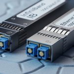
| FS.com SFP-10G-SR (example) | 10G | 850 nm | 300 m (OM3) / 400 m (OM4) | LC | Yes (bias, Tx/Rx power, temp) | 0 to 70 C (varies by SKU) | ~0.8 to 1.5 W |
| Cisco SFP-10G-SR (example) | 10G | 850 nm | 300 m (OM3) / 400 m (OM4) | LC | Yes (vendor DOM registers) | 0 to 70 C | ~0.8 to 1.5 W |
| Finisar FTLX8571D3BCL (example) | 10G | 850 nm | 300 m (OM3) / 400 m (OM4) | LC | Yes (DOM) | -5 to 70 C (varies by part) | ~1 W class |
| FS.com SFP-25G-SR (example) | 25G | 850 nm | 70 m (OM3) / 100 m (OM4) | LC | Yes (DOM) | -5 to 70 C | ~1.5 to 2.5 W |
Always confirm the exact SKU and its DOM register map in the manufacturer datasheet. For optical compliance and reach, verify the transceiver’s target fiber type against your installed cabling plant. For reference reach and Ethernet PHY behavior, use [Source: IEEE 802.3] and vendor datasheets for each specific module model.
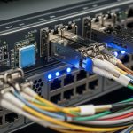
Deployment scenario: threshold tuning in a 3-tier data center
In a 3-tier data center leaf-spine topology with 48-port 10G ToR switches, each leaf uses 24 uplinks at 10G over OM4 with LC connectors on a standard patch panel. A monitoring system polls DOM every 60 seconds and correlates receive-power drift with interface error counters. After a planned cleaning event in one row, engineers observed receive-power recovered by about 1.8 dB within the same day, while bias current returned to prior levels. They then adjusted the warning thresholds from a static absolute value to a drift-based rule: trigger a ticket only if receive power drops more than 2.0 dB over 6 consecutive polls and CRC errors increase.
Result: the team reduced “noise alarms” by roughly 35% while still catching a real connector contamination issue within 12 hours of onset on a different leaf. Without threshold maintenance, the same incident might have waited until hard link degradation, because the built-in module alarm remained below its own register limits.
Selection criteria checklist for DDM threshold transceiver maintenance
Use this ordered checklist when you define maintenance policies and set monitoring thresholds across vendors and sites.
- Distance and optical budget: verify OM type, patch loss, and expected insertion loss; set thresholds relative to your link budget margins.
- Data rate and PHY behavior: ensure your switch and optics match the IEEE 802.3 interface type and lane mapping expectations.
- Switch compatibility: confirm DOM polling works in your specific switch model; some platforms throttle DOM reads or map warnings differently.
- DOM support and register consistency: validate availability of Rx power, Tx power, bias current, and temperature in the DOM registers your monitoring expects.
- Operating temperature range: align threshold logic with the module’s rated range; elevated temperature can cause drift even if optics are fine.
- Vendor lock-in risk: if you rely on vendor-specific threshold registers, document fallback behavior for third-party optics.
- Operational workflow fit: ensure alerts route to the right runbook steps (inspection, cleaning, replacement) with ownership and escalation timers.
Practical threshold tuning steps
- Pull DOM history for a representative set of healthy links (at least 20 interfaces) and compute median and percentile bands for Rx power, bias current, and temperature.
- Set warning thresholds to detect drift but avoid single-event spikes; use a persistence window (for example, 6 to 10 polls).
- Set alarm thresholds to match your outage prevention goals: trigger immediate escalation when alarms correlate with rising CRC/FEC errors.
- Re-baseline after any physical layer change: cleaning, patch re-termination, or cabinet airflow modifications.
Common mistakes and troubleshooting tips (with root causes)
Below are failure modes that repeatedly show up in audits of DDM threshold transceiver maintenance programs. Each includes root cause and a field-ready fix.
Alerts trigger on every minor DOM fluctuation
Root cause: thresholds configured as static absolute values with no persistence window, combined with normal temperature and laser compensation variation.
Solution: implement drift-based rules and require sustained deviation across multiple polls; add correlation with interface CRC/FEC errors before ticket creation.
“Healthy DOM” but the link still degrades
Root cause: the monitored parameters do not reflect the real impairment path (for example, fiber contamination raises insertion loss but DOM remains within vendor alarm limits), or the threshold logic is too permissive.
Solution: compare DOM trends against error counters; if BER/CRC errors rise while DOM stays quiet, treat it as a physical layer problem and inspect connectors and patch cords for contamination or micro-bends.
Misinterpretation of bias current vs Tx power
Root cause: operators interpret rising bias current as “more power output,” but compensation behavior can keep Tx power stable while bias current increases due to aging or temperature effects.
Solution: track both bias current and output power together; rising bias with flat output is a strong indicator of aging or thermal stress, and you should preemptively schedule replacement.
Thresholds copied across sites with different cabling loss
Root cause: identical thresholds applied to links with different patch panel layouts, different OM ratings, or different cleaning/termination quality.
Solution: compute per-site baselines and set thresholds relative to measured medians; keep a margin tied to your link budget rather than relying on a global number.
Cost and ROI note: keeping maintenance targeted, not expensive
In most enterprises, optics themselves cost less than downtime. Typical street pricing varies widely by brand and channel, but a 10G SR transceiver often falls in the range of $20 to $80 per module for common OEM or compatible SKUs, while higher density 25G/40G modules can cost $60 to $200+ depending on reach class and vendor. The bigger cost is operational: labor and truck rolls. A well-tuned DDM threshold transceiver maintenance program reduces emergency replacements and shortens mean time to detect (MTTD).
TCO considerations: OEM optics may include better compatibility guarantees and documentation, but third-party optics can be viable if they expose consistent DOM registers and pass your switch vendor compatibility checks. Expect failure rates to vary by manufacturer and environment; manage risk by validating DOM behavior in a pilot group and by recording real-world DOM trajectories during scheduled maintenance windows.
FAQ
How do I confirm that my switch is reading the right DOM thresholds?
Check the switch CLI or management interface for DOM fields and validate that receive power, bias current, and temperature are populated for each module. Then compare warning/alarm flags against the module’s datasheet and, if available, the vendor DOM threshold registers. If the platform reports only partial fields, your monitoring thresholds must be adjusted to avoid blind spots.
Should I trust the module built-in alarm limits?
Built-in alarms are a safety net, not a maintenance strategy. They are designed to protect the link from catastrophic degradation, not to predict failures early enough for planned replacement. Use them as a hard escalation trigger, while your warning thresholds should come from your measured baselines and error correlations.
What polling interval is practical for DDM threshold transceiver maintenance?
A common operational choice is 30 to 120 seconds. Faster polling can increase load on management planes and produce noise from short-lived spikes. Slower polling can delay detection; for rapidly changing physical-layer issues like connector contamination, you may want closer to 60 seconds.
Can I use the same thresholds for different transceiver vendors?
Only if the DOM meanings and register scaling are consistent across vendors, and only after you confirm units and scaling. Even when fields look the same, vendors can implement different internal threshold policies. Start with per-vendor baselines and then standardize your drift-based rules once you have comparable distributions.
What is the fastest way to distinguish contamination from laser aging using DOM?
Connector contamination usually shows up as receive-power loss and may correlate with changes after patch moves or cleaning events. Laser aging often presents as increased bias current and slower degradation in output characteristics over time. The fastest confirmation is correlating DOM trends with physical inspection results and measuring optical power after cleaning.
Where do IEEE standards fit into DDM maintenance?
IEEE 802.3 defines the Ethernet PHY behavior and link requirements for each interface type and reach class. DOM and DDM threshold registers are not fully standardized to the same degree across vendors, so you use IEEE standards to validate link type and performance expectations, and use vendor datasheets to interpret DOM scaling and threshold behavior.
DDM threshold transceiver maintenance is most effective when it combines accurate DOM interpretation, per-site baselines, and a workflow that ties alarms to physical-layer actions. Next step: implement a drift-based warning model and run a one-month pilot across your most critical uplinks using related topic for your monitoring policy template.
Author bio: Field-tested network reliability writer focused on optical transport, transceiver telemetry, and operational runbooks. Previously supported NOC teams by instrumenting DOM-driven alerting and validating optics across multi-vendor switch fleets.