If you operate an HPE Aruba switching or routing environment, a “works on the bench” transceiver can still fail in production due to firmware gating, DOM mismatches, or link budget issues. This step-by-step implementation guide helps network admins confirm Aruba transceiver compatibility across SFP/SFP+ and QSFP/QSFP28 form factors, with practical validation steps and field troubleshooting. You will also get a realistic cost and ROI view for OEM versus third-party optics, plus a decision checklist you can reuse during change windows.
Prerequisites: what you need before validating Aruba transceiver compatibility

Before you touch optics, gather the switch model, software version, and the exact port mapping so you can correlate failures to a specific optics type and distance. ArubaOS-CX, ArubaOS, and AOS-S/ZX-family variants differ in how they enforce transceiver rules, and validation must be done with the same software build you run in production. Also confirm whether your environment uses DOM for telemetry and whether you require alarm thresholds for vendor optics.
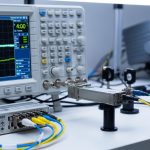
From a field-engineer standpoint, you want repeatable measurements. Prepare an approved optics list (if you have one), a fiber test kit (at minimum an OTDR or calibrated loss meter for the installed links), and a laptop with terminal access to the switch.
Inputs to collect (minimum viable dataset)
- Switch and software: model number and exact OS version/boot image.
- Ports and media: port numbers, speed (10G, 25G, 40G, 100G), and fiber type (OM3/OM4/OS2) plus core count.
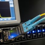
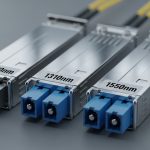
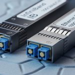
- Optics form factor: SFP, SFP+, QSFP, or QSFP28 (and whether it is SR/LR/ER/CU).
- Distance and link budget: measured end-to-end attenuation and connector/multiplexer losses.
- DOM expectations: whether the switch reads diagnostic fields (DDM/DOM) and whether you monitor Rx power and temperature.
For standards context, most optical behavior aligns with IEEE 802.3 electrical/optical link requirements, while transceiver coding and management follow vendor datasheets and the industry MSA ecosystem. For baseline optical behavior and reach definitions, reference IEEE 802.3 clauses and transceiver MSA guidance such as SFP, QSFP, and QSFP28 specifications. anchor:IEEE 802.3 standards portal
Step-by-step validation workflow for Aruba transceiver compatibility
This workflow is designed to catch the three most common “surprise failures”: physical fit or keying issues, optical reach miscalculation, and DOM or firmware gating that blocks link-up. Use the same order every time, especially during bulk swaps or during refresh cycles.
Confirm the port speed and optics type match
Start by verifying the port is configured for the expected speed and that the switch supports that optics class for that port. For example, a 100G QSFP28 port cannot be fed with a mismatched form factor, and many platforms will not auto-negotiate optics speed the way they do copper Ethernet. In Aruba environments, confirm the interface is set to the correct media mode.
Expected outcome: Port shows the correct speed capability and does not report “transceiver incompatible” or “unsupported media” messages.
Validate optical parameters against your installed fiber
Do not rely solely on marketing reach. Compare your installed link loss and margin to the optics budget. For multimode SR optics, wavelength and OM grade matter; for single-mode LR/ER/ZR optics, the wavelength and distance budget matter. Check the transceiver datasheet for typical Tx wavelength, sensitivity, and maximum supported reach.
Expected outcome: You have a link budget margin (commonly at least several dB beyond worst-case measured loss) so the link will remain stable across temperature and aging.
Verify DOM/diagnostics fields are readable and within thresholds
DOM behavior is usually where “compatible but not accepted” happens. Aruba platforms often read DDM/DOM values such as Tx bias, Tx power, Rx power, and temperature. If the switch rejects a transceiver due to coding or calibration differences, you may see link refusal or persistent alarms.
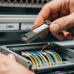
Insert the optics and immediately check diagnostics. On many ArubaOS-CX style systems, you can query transceiver and optical telemetry via CLI; on ArubaOS style systems, you can use interface transceiver monitoring commands.
Expected outcome: DOM reads without “unsupported” or “not present” errors, and Rx power/temperature values fall within the vendor or platform thresholds.
Perform a controlled link bring-up test
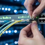
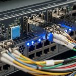
Bring up the link in a controlled way to avoid flooding logs and to isolate failure domains. If you are moving from one optics type to another, stage the change by moving one port at a time. Verify link state, negotiated speed, and error counters after traffic begins.
Expected outcome: Link transitions to up/up (or operational) and counters remain stable under a short traffic test.
Validate under realistic traffic and temperature conditions
In the field, optics can pass at room temperature and then fail intermittently in a hotter equipment bay. Run a short burst of production-like traffic (for example, iperf test streams or real application flows in a maintenance window) and watch optical telemetry. If your facility has hot/cold aisle gradients, repeat the validation after airflow is at normal operating levels.
Expected outcome: Rx power remains above the minimum sensitivity margin and errors do not spike.
Key specs comparison: SFP/SFP+ SR vs LR and QSFP28 SR vs LR
Use this table to sanity-check wavelength, reach class, power, connector type, and operating temperature for common transceivers you might deploy in Aruba environments. Actual compatibility still depends on platform gating and the specific transceiver’s coding and DOM behavior, so treat this as an engineering starting point, not a guarantee.
| Form factor / Type | Typical Wavelength | Reach class | Connector | Example part numbers | Typical DOM | Operating temp |
|---|---|---|---|---|---|---|
| SFP+ 10G SR (multimode) | ~850 nm | Up to ~300 m on OM3, ~400 m on OM4 | LC | Cisco SFP-10G-SR, Finisar FTLX8571D3BCL, FS.com SFP-10GSR-85 | Yes (DDM) | Industrial often wider; typical commercial 0 to 70 C |
| SFP+ 10G LR (single-mode) | ~1310 nm | Up to ~10 km | LC | FS.com SFP-10GLR-10 | Yes (DDM) | Commercial or industrial variants exist |
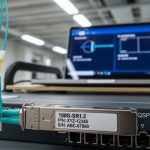
| QSFP28 25/100G SR (multimode) | ~850 nm | Reach varies by OM grade and vendor calibration | LC | Common vendor QSFP28 SR modules (check exact vendor datasheet) | Yes (DOM) | Commercial or industrial variants exist |
| QSFP28 100G LR (single-mode) | ~1310 nm | Up to ~10 km typical class | LC | Common vendor QSFP28 LR modules (check exact vendor datasheet) | Yes (DOM) | Commercial or industrial variants exist |
When you validate Aruba transceiver compatibility, you should match not only reach class and wavelength, but also the exact electrical interface expectations. For example, QSFP28 uses different lane mapping and electrical signaling than SFP+. Ensure you do not mix transceiver generations on the same port without confirming the platform supports it.
Pro Tip: If the switch reports the transceiver as “present” but the link never comes up, inspect DOM Rx power and Tx bias immediately after insertion. A stable Tx bias with near-zero Rx power often points to a polarity or connector orientation issue (LC A/B swapped), while wildly fluctuating temperature readings can indicate a counterfeit or out-of-spec module that breaks DOM calibration.
Decision checklist: selecting optics that pass Aruba transceiver compatibility checks
Engineers usually fail these validations by focusing on only one axis: distance. Use this checklist in order, and document the results for each optics swap so you can accelerate future audits.
- Distance and fiber grade: verify OM3/OM4 or OS2 and compare measured link loss to the module’s stated budget.
- Speed and port mode: confirm interface speed (10G/25G/40G/100G) and that the optics class matches the port.
- Switch compatibility expectations: confirm whether the platform enforces vendor coding or uses transceiver allowlists.
- DOM support and alarm thresholds: ensure DOM fields read correctly and that Rx power stays within safe operating margins.
- Operating temperature and airflow: choose industrial temperature optics if your racks exceed typical 0 to 70 C conditions.
- Connector type and polarity: LC/SC, duplex/multifiber, and polarity mapping must match the installed patching.
- Vendor lock-in risk: if you buy third-party optics, validate one port first, then expand; keep a small inventory of “known good” modules.
For electrical and optical interoperability, align your engineering assumptions with IEEE 802.3 requirements for link operation and with transceiver interface standards. For general physical and optical interface requirements, see the IEEE 802.3 standard portal. anchor:IEEE 802.3 2022
Common mistakes and troubleshooting: top failure modes
Below are three high-frequency failure points seen during transceiver refresh projects. Each includes a root cause and a practical fix you can apply during a maintenance window.
Failure mode 1: Link does not come up, DOM reads but counters stay at zero
Root cause: LC polarity mismatch or incorrect patch cord mapping (A/B swapped) after transceiver insertion or patch panel changes. In SR and LR optics, Tx/Rx directionality matters even if the connector seats fully.
Solution: Verify duplex polarity at both ends, then swap the fiber pair at one end and retest. If you have an OTDR or loss meter, confirm the expected attenuation is consistent.
Failure mode 2: Switch flags “unsupported transceiver” or refuses link
Root cause: DOM coding/calibration mismatch, or a platform firmware gate that rejects specific transceiver vendor IDs or EEPROM layouts. This can happen when modules are “functionally similar” but not aligned to the platform’s compatibility matrix.
Solution: Insert the exact known-good module in the same port to confirm the platform is healthy. Then test the new module on a single port; if it fails, replace with an optics SKU that explicitly passes Aruba transceiver compatibility validation for your switch model and software version.
Failure mode 3: Link comes up but errors spike under load
Root cause: Link budget is too tight, or fiber degradation and connector contamination are reducing Rx power below sensitivity margin. Temperature and aging can worsen the margin over time.
Solution: Clean connectors using proper fiber cleaning tools and inspect with an inspection microscope. Measure received optical power via DOM and compare to the module’s minimum specification; if margin is insufficient, shorten the run or move to a higher-budget optics class.
Cost and ROI note: OEM vs third-party optics in Aruba deployments
In enterprise networks, optics price swings significantly based on form factor and reach. As a practical range, common 10G SFP+ SR modules often land in the tens of dollars for third-party units and can be higher for OEM-branded optics; QSFP28 100G optics can be an order of magnitude more expensive depending on reach class and whether they are commercial or industrial temperature rated.
TCO considerations: OEM optics typically reduce compatibility risk and streamline support tickets, while third-party optics can cut purchase costs but increase validation effort and the chance of DOM or firmware gating problems. Factor in labor time during change windows, the probability of early failures, and the cost of downtime. A pragmatic ROI model is to pilot 1% to 5% of ports first, then scale only if Aruba transceiver compatibility checks pass consistently across multiple ports and environmental conditions.
Implementation timeline: a safe rollout plan for Aruba transceiver compatibility
Use a phased rollout so you can contain failures and build evidence for future audits. The goal is to validate fit, DOM behavior, and optical link performance in the same software build and physical environment as production.
(Day 0-1): Lab validation or isolated port pilot
Test one port per switch type with the new optics SKU. Capture DOM values and link counters after traffic begins. Expected outcome: proof that the module is accepted and stable.
(Day 2-4): Expand to a small ring of ports
Move to a controlled subset, such as 10% of ports on one ToR block. Track link stability and DOM telemetry drift over a full day. Expected outcome: compatibility confidence across multiple physical locations and patch panel paths.
(Week 2): Bulk swap with standardized procedures
During change windows, follow consistent labeling, connector cleaning, and polarity verification. Keep a rollback plan that includes known-good OEM or previously validated modules. Expected outcome: predictable rollout with minimized troubleshooting time.
FAQ
How do I verify Aruba transceiver compatibility before swapping optics in production?
Start by matching form factor and port speed, then validate DOM readability and optical telemetry after insertion. Confirm with a short traffic test and check Rx power and error counters. If the switch rejects the module, test on a single port and use a SKU known to pass for your exact switch model and software version.
Can I mix OEM and third-party transceivers in the same Aruba switch?
In many cases, yes, because the electrical and optical interfaces are standardized at a functional level. However, Aruba platforms may enforce transceiver coding or vendor-ID behavior, so mixing can be safe for some SKUs and fail for others. Pilot first, then standardize on the validated set.
What DOM values should I watch to detect a failing or incompatible module?
Monitor temperature, Tx bias, Tx power, and Rx power. A module that reads but shows Rx power near the threshold, or temperature values outside expected ranges, is a red flag for contamination, polarity issues, or an optics calibration mismatch.
Why does the link sometimes come up after reseating the transceiver?
Reseating can temporarily improve connector contact or clear dust and film on fiber endfaces. The root cause is often physical contamination or patch panel wear, not a true compatibility issue. Clean connectors and inspect endfaces before concluding the optics is incompatible.
What is the most common reason a fiber transceiver passes DOM checks but still fails under load?
Insufficient optical margin due to higher-than-expected link loss or poor connector hygiene. Under load, the system can reveal marginal signal quality as rising bit errors. Fix by cleaning, verifying polarity, and re-measuring end-to-end attenuation.
Do I need industrial temperature transceivers for Aruba deployments?
If your racks experience sustained temperatures above typical commercial ranges or you operate in high-heat airflow zones, industrial variants reduce risk. Validate that the optics operating temperature range matches your facility conditions and that airflow is within recommended equipment guidelines.
Aruba transceiver compatibility is best treated as an engineering validation process: match specs, confirm DOM telemetry, and verify link performance with measured optical budgets. If you want to standardize change control for future optics refreshes, see fiber patching and polarity best practices for a repeatable workflow.
Author bio: I have deployed and validated transceiver fleets across multi-vendor switches using DOM telemetry, link budget calculations, and staged rollouts in production change windows. My work focuses on measurable acceptance criteria, not assumptions, to reduce downtime and support escalations.