Your switch vendor says “it should work,” your lab says “it does not,” and your pager says “good luck.” This article helps network engineers and field techs understand how QSFP-DD backward compatible optics behave when you plug them into QSFP28 ports, what to verify before you burn a weekend, and how to troubleshoot the classic failure modes.
You will get a practical compatibility checklist, a head-to-head comparison of typical transceiver options, and deployment notes from real leaf-spine and high-density server racks. Expect no hand-waving: we will talk power budgets, DOM behavior, lane wiring, and the “yes, but” limits that matter.
What “QSFP-DD backward compatible” actually means on hardware

QSFP-DD is a higher-density optical form factor intended for double the lanes and higher aggregate bandwidth than QSFP28. “Backward compatible” is often used loosely in marketing, so the field reality is that compatibility depends on the port cage, the switch ASIC, and the transceiver’s electrical interface. In many systems, a QSFP-DD module can operate at QSFP28-compatible speeds only if the cage and firmware support the required lane mapping and signaling.
IEEE Ethernet standards define signaling behaviors, but the module-to-platform agreement is still vendor specific. For Ethernet and optics, the broad foundation is in IEEE 802.3 families and the transceiver specifications from vendor datasheets; for module management, DD/DOM behavior is governed by the transceiver programming model used by the platform. See [Source: IEEE 802.3] and [Source: IEEE 802.3 Ethernet] for baseline framing and electrical requirements. For practical compatibility behavior, always validate against the switch vendor’s optics matrix and transceiver support list.
Lane mapping and why “keying” is not the whole story
Even when a module physically fits, the switch must understand how those lanes map to the internal SerDes. QSFP28 uses 4 lanes; QSFP-DD typically uses 8 lanes at the higher-rate modes. If the switch expects 4-lane signaling but the module drives 8-lane patterns, you can see symptoms like link flaps, no link, or runs at a fallback speed that still fails application traffic.
Bottom line: physical insertion and connector keying are necessary but not sufficient. The port cage must support the electrical profile and the firmware must enable the correct speed and lane mode.
QSFP-DD vs QSFP28 optics: performance and electrical differences
Let’s do a head-to-head on what engineers actually care about: reach, wavelength, power, and temperature behavior. When the goal is QSFP28 port use, the key question is whether the QSFP-DD optics you buy provide a supported operating mode that the QSFP28 cage can negotiate.
| Spec / Factor | QSFP28 Typical | QSFP-DD Typical (QSFP28-mode operation varies) |
|---|---|---|
| Form factor | QSFP28 (4 lanes) | QSFP-DD (8 lanes at high-rate) |
| Data rate range | 25G per lane aggregate commonly 100G (4×25) | Often 100G/200G class; QSFP28-compatible modes depend on platform |
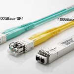
| Common wavelengths (SR) | 850 nm multimode | Often 850 nm multimode for SR variants |
| Reach (SR examples) | Up to roughly 100 m on OM4; varies by vendor and optics grade | May match QSFP28 SR reach in compatible modes; verify with vendor reach tables |
| Connector | LC duplex (SR) commonly | LC duplex commonly for SR; check exact part number |
| Power budget | Typically lower than high-rate QSFP-DD; verify module TDP | Can be higher; platform must support the cage power limits |
| DOM support | Standard DOM for optics management | DOM usually supported; fields and thresholds can differ |
| Operating temperature | Commonly industrial or commercial variants (verify) | Often similar classes; verify exact spec for your BOM |
For concrete part-number examples, you will see QSFP28 SR modules like Cisco SFP-10G-SR in other ecosystems and many 100G QSFP28 SR optics from major suppliers. On the QSFP-DD side, look at vendor datasheets for examples such as Finisar/NeoPhotonics style families (for instance, optical SR variants like FTLX8571D3BCL are QSFP-class examples in the ecosystem) and third-party offerings (for example, FS.com QSFP-DD SR families). Because exact part mappings vary, you should treat datasheet values as a starting point and confirm in your switch’s compatibility list.
Authority references: [Source: IEEE 802.3] for Ethernet behavior, [Source: ANSI/TIA-568] for cabling basics, and [Source: vendor transceiver datasheets] for reach and power.
Compatibility reality check: QSFP28 ports, firmware, and DOM
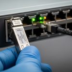
Here is the part that saves you time: the switch decides whether QSFP-DD can run in a QSFP28 port. Even if the module advertises a QSFP28-capable mode, the platform must support the required negotiation and lane configuration. In practice, you validate with three items: the optics compatibility matrix, the port speed capability, and the DOM behavior that the platform uses for alarm thresholds and vendor identification.
Start by checking the switch model’s optics support list. Many enterprise switches publish a matrix of “module type, part number, supported speed, and verified wavelength.” If your QSFP-DD part is not listed for that exact port type, treat it as a lab science experiment, not production magic.
Decision checklist you can actually run during install
- Distance and fiber type: confirm OM4 vs OM3, patch cord loss, and total channel attenuation budget. Use ANSI/TIA cabling practices to validate link budgets. [Source: ANSI/TIA-568]
- Switch compatibility: confirm the exact switch model and port speed support for QSFP-DD modules in QSFP28-mode operation.
- Budget and power limits: verify module TDP against the port cage power budget; high-power QSFP-DD optics may be rejected or throttle.
- DOM support and thresholds: ensure the platform reads DOM fields without “unsupported vendor ID” errors; confirm alarms and diagnostics are functional.
- Operating temperature: match the module temperature class to your environment; rooftop server rooms and boiler-adjacent closets are not “standard.”
- Vendor lock-in risk: check whether third-party optics are supported for your OS version; plan spares accordingly.
Pro Tip: In the field, “it links at all” is not the victory condition. Verify negotiated speed and lane mode in the switch CLI, then confirm optical power and error counters after a full traffic burst. Some platforms will fall back silently, leaving you with a “green link, red performance” situation that looks fine for five minutes and then faceplants under load.
Head-to-head: when QSFP-DD on QSFP28 ports is a win vs a trap
Think of this as two scenarios: (1) you are trying to standardize optics across mixed generations, or (2) you are trying to stretch a budget by reusing existing port hardware. In scenario (1), QSFP-DD optics can help if your platform supports the fallback mode cleanly. In scenario (2), you risk compatibility friction, unpredictable negotiation, and increased troubleshooting time.
Scenario A: standardized optics in a mixed rack
In a data center with planned refresh cycles, you may have some switches with QSFP28 cages and later add models with QSFP-DD support. A QSFP-DD backward compatible module can reduce the number of SKUs you stock, but only if the older switch accepts the module and negotiates the supported mode. Validate during pilot: run link stability tests for at least 30 minutes with continuous traffic and monitor optical RX power and CRC/packet error counters.
Scenario B: budget stretching on legacy QSFP28 ports
If the QSFP-DD module is not explicitly supported for QSFP28 cages, you may see “link up” followed by intermittent loss during temperature swings or cable movement. That is often a sign of marginal signal integrity settings, lane mapping mismatch, or oversubscription behavior in the switch fabric. If you must proceed, choose modules with clearly documented compatibility and ensure you use validated patch cords and attenuations.
Common mistakes and troubleshooting tips for backward compatibility
Below are concrete failure modes I have seen during rollouts. Treat these as a checklist for the next time your link refuses to behave like it pays rent.
Physical fit but no link: unsupported electrical profile
Root cause: The module inserts, but the QSFP28 cage does not support the QSFP-DD electrical signaling mode required for negotiation. This can happen after an OS update changes optics handling, or when the module expects a different lane mapping.
Solution: Confirm the module part number is listed for the switch model and OS version. Force the port speed to the expected QSFP28 rate (if supported), then re-check link state and DOM read status.
Link flaps under load: power budget or thermal throttling
Root cause: QSFP-DD optics may draw more power than the port cage budget allows, leading to partial initialization and unstable transmitter behavior. Temperature swings can trigger marginal operation even if idle looks fine.
Solution: Measure cage power availability if the platform exposes it, and run a sustained traffic test while monitoring DOM temperature and optical bias currents. If temperatures exceed module spec, improve airflow or swap to a lower-power compatible optic.
CRC errors with “green” link: fiber/channel loss and patch cord mismatch
Root cause: Backward compatibility does not fix a bad fiber plant. If the optics are operating at a different effective budget than expected, OM3/OM4 mismatch, dirty LC connectors, or excessive patch cord loss can drive error counters up.
Solution: Clean connectors using proper procedures, then verify link attenuation with a light meter or OTDR. Replace patch cords with validated lengths and ensure the total channel loss matches the vendor’s reach budget for the actual mode.
DOM alarms: unsupported vendor ID or missing diagnostics fields
Root cause: Some third-party QSFP-DD modules provide DOM fields that the platform expects differently, causing threshold misreads or warnings that mask real issues.
Solution: Confirm DOM compatibility in the optics matrix. If you see repeated “DOM read failure” messages, try a known-good module from the same vendor family and compare reported fields.
Cost and ROI: OEM vs third-party optics in a QSFP28-to-QSFP-DD story
Realistic pricing depends on speed and reach, but a typical range you might see in procurement is roughly $80 to $250 per QSFP28 100G SR and $150 to $450 per QSFP-DD 200G/100G-class SR depending on brand, binning, and DOM features. OEM optics often cost more but may have lower operational risk because they match the vendor’s compatibility matrix. Third-party modules can reduce upfront cost, but they may increase incident tickets and time-to-resolution if negotiation or DOM behavior differs between OS releases.
TCO is mostly about failure rates, swap logistics, and downtime cost. If your environment is high-availability and your incident response is expensive, paying for OEM support can be cheaper than the “mystery module” tax. If you run large fleets with disciplined validation, third-party optics can be a reasonable ROI, but only after you lock compatibility to your exact switch model and software version.
Decision matrix: choose the safer path for your port generation
Use this matrix to decide whether QSFP-DD backward compatible modules are appropriate for your QSFP28 cages.
| Requirement | Best Fit | Why |
|---|---|---|
| You must use existing QSFP28 ports | QSFP28 module (verified) | Lowest compatibility risk; matches port signaling expectations |
| You want fewer SKUs across mixed racks | QSFP-DD module only if explicitly supported | Reduces inventory variety, but requires validated fallback mode |
| Your budget is tight and spares are plentiful | Third-party only after pilot validation | Lower cost, but DOM and negotiation differences can raise troubleshooting time |
| You need predictable diagnostics and alarm behavior | OEM or tightly validated third-party | Consistent DOM field mapping and threshold handling |
| You operate in hot or variable airflow | Optics with verified temperature class | Protects against thermal throttling and marginal optical bias behavior |
Which Option Should You Choose?
If you are deploying in a stable environment where QSFP28 ports dominate, choose verified QSFP28 optics and move on with your life. If you are mid-refresh and want inventory simplification, choose QSFP-DD backward compatible modules only when your switch vendor explicitly supports the exact QSFP-DD part number for QSFP28-mode operation, and after a pilot that confirms negotiated speed and error counters under load.
Next step: check your switch’s optics matrix, then validate fiber channel loss and DOM diagnostics for the exact optics you plan to install using optics compatibility matrix workflow.
FAQ
Can a QSFP-DD module physically plug into a QSFP28 cage?
Often yes, but physical fit does not guarantee electrical or firmware compatibility. You must confirm the switch model supports QSFP-DD modules in a QSFP28-capable mode and that lane mapping and signaling negotiation are supported.
Will QSFP-DD backward compatible optics always fall back to QSFP28 speeds?
No. Some platforms may reject the module, negotiate a different mode, or link with reduced capability that still fails performance targets. Always verify the negotiated speed and check optical and error counters after sustained traffic.
What fiber issues look like optics incompatibility?
Dirty connectors, excessive patch cord loss, OM3/OM4 mismatch, and aggressive bends can all cause link instability and CRC errors. Clean and validate the fiber plant first, then reassess compatibility if the channel loss is within the vendor budget.
Do I need DOM compatibility for troubleshooting?
Yes, DOM data is how you confirm optical power, temperature, and diagnostic thresholds. If DOM reads fail or thresholds behave oddly, you may miss the real root cause behind flaps and errors.
Is it worth buying third-party QSFP-DD optics for QSFP28 ports?
It can be, but only after you pilot with your exact switch model, OS version, and fiber plant. If your organization cannot tolerate increased troubleshooting time, OEM optics usually provide a smoother operational experience.
Where should I check official compatibility?
Use the switch vendor’s optics compatibility matrix and the transceiver datasheet for electrical and reach requirements. Cross-check both, because datasheets describe module capabilities while matrices describe platform acceptance.
Author bio: I design optics and switch interfaces with a focus on real-world failure modes, field diagnostics, and user-friendly operational clarity. I have deployed and troubleshot high-density Ethernet transceiver rollouts in production data centers, where “it links” is only the beginning.