In modern fiber networks, the hardest failures are the ones you only notice after traffic drops. A DDM DOM optical transceiver changes that by exposing real-time telemetry like laser bias, received power, and temperature so teams can predict degradation. This article helps network engineers, data center operators, and procurement leads evaluate DDM/DOM for reliability, compatibility, and total cost of ownership.
How DDM/DOM telemetry works inside an optical transceiver

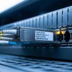
Digital Diagnostic Monitoring (DDM) and its vendor-defined DOM implementation expose optical and electrical measurements through a serial management interface. Most pluggable optics follow the monitoring model defined by IEEE 802.3 for digital diagnostics, using an I2C-like management channel accessible by the host switch or transceiver module. In practice, the module reports parameters such as laser bias current (mA), transceiver supply voltage (V), laser temperature (C), and received optical power (dBm). When these values cross vendor thresholds, many platforms log events or trigger alarms before the link fully fails.
DDM vs DOM: why the names both matter
“DDM” is the common term for digital diagnostics in many engineering teams; “DOM” is frequently used in vendor catalogs to indicate the same class of telemetry. Compatibility is not guaranteed solely by naming: some vendors label features as DOM but implement different threshold defaults, scaling, or alarm behavior. The safe approach is to confirm the exact diagnostic page mapping and alarm support for your target switch family, not just whether the module “has DOM.”
What telemetry can predict, not just detect
Field teams typically use DDM/DOM to correlate symptoms with physical layer stress. For example, a gradual received power decline paired with stable temperature can indicate fiber attenuation growth or connector contamination. A rising laser bias current with constant received power often points to aging laser output or degraded internal optics. This is why engineers treat DDM/DOM as a reliability signal rather than a dashboard novelty.
Pro Tip: In many deployments, the earliest actionable indicator is not received power alone; it is the combination of laser bias current trend and temperature stability. A slow bias increase with temperature within normal range often precedes a bigger optical output drop, giving maintenance teams a wider intervention window.
Specifications that actually affect link behavior
Not every DDM-capable module behaves the same under load, especially across different wavelengths and reach classes. When selecting a DDM DOM optical transceiver, engineers must verify wavelength, data rate, fiber type, optical budget, connector style, and the operating temperature range. Equally important is whether the module provides standards-compliant diagnostics and whether the host platform reads them correctly.
Key spec comparison: common 10G SR module classes
The table below compares representative 10G short-reach optics that typically support digital diagnostics. Exact values vary by vendor and revision, so use this as a decision frame and confirm against the specific datasheet.
| Spec | 10G SR (850 nm) Example | 10G LR (1310 nm) Example | Typical Impact for DDM/DOM |
|---|---|---|---|
| Data rate | 10.3125 Gb/s | 10.3125 Gb/s | Telemetry scaling and thresholds are tied to module design |
| Wavelength | 850 nm | 1310 nm | Different optics have different aging patterns and power drift |
| Reach | Up to ~300 m (OM3/OM4 class) | Up to ~10 km | DDM helps detect marginal links earlier in both cases |
| Connector | LC duplex | LC duplex | Connector contamination affects received power readings |
| Power budget (typical) | Designed for short-reach losses | Designed for longer attenuation | Thresholds should match the host’s expected link margin |
| Operating temperature | 0 to 70 C (commercial) | -40 to 85 C (extended, varies) | Temperature telemetry becomes critical in harsh environments |
| DDM/DOM parameters | Bias current, supply voltage, temperature, Rx power | Bias current, supply voltage, temperature, Rx power | Host must interpret diagnostics correctly |
Concrete examples you can sanity-check
When evaluating real parts, engineers often look for models like Cisco SFP-10G-SR equivalents for SR, or vendor-listed LR modules with digital diagnostics. Example optics commonly referenced in the market include Finisar/NeoPhotonics family parts such as FTLX8571D3BCL (10G SR, 850 nm) and FS.com catalog items like SFP-10GSR-85. Always validate the exact DOM/DDM feature set in the datasheet and confirm that the host switch accepts the module ID and diagnostics pages.
For standards context, digital diagnostics are aligned with the transceiver management model documented across Ethernet optics guidance and IEEE 802.3 specifications. Consult the standard and vendor datasheets before assuming interoperability. [Source: IEEE 802.3 Working Group materials] [Source: Cisco SFP product documentation] [Source: vendor transceiver datasheets]
Deployment scenario: using DDM to stop a silent degradation
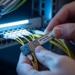
Consider a 3-tier data center leaf-spine topology with 48-port 10G ToR switches. Each ToR uplinks to aggregation using 10G SR optics over OM4 fiber, totaling 96 active links per rack pair during peak hours. Over a quarter, the operations team sees intermittent CRC errors on a subset of uplinks, but the links stay “up” long enough to avoid triggering immediate failover. By enabling DOM alarms, the team monitors received power and laser bias current. They observe that five modules show Rx power trending down by 1.2 to 1.8 dB over three weeks while bias current steadily rises and temperature remains within normal range. Maintenance then cleans the affected LC connectors and verifies patch panel integrity.
After cleaning and re-termination, those same ports recover link margin and error counters return to baseline within 24 hours. Without DDM/DOM visibility, the team likely would have waited for a hard outage, then performed reactive troubleshooting across multiple racks. In an environment where a technician visit costs a day of schedule impact, this predictive maintenance approach can pay back quickly.
Selection criteria and decision checklist for DDM DOM optics
To choose the right DDM DOM optical transceiver, engineers typically run a structured filter. Below is an ordered checklist that balances reliability, interoperability, and ROI.
- Distance and optical budget: Confirm fiber type (OM3/OM4/OS2), connector losses, and expected attenuation. Ensure the module reach class matches your engineered link margin.
- Data rate and form factor: Validate SFP vs SFP+ vs QSFP28 (or other) and the exact data rate required by your switch and optics profile.
- Switch compatibility: Confirm the host platform reads diagnostics and supports third-party optics if that matters. Some platforms enforce strict module IDs or have partial DOM alarm support.
- DDM/DOM support details: Verify which telemetry fields are exposed (Rx power units, bias current scaling, threshold flags) and whether alarms are supported.
- Operating temperature range: Match your environment. For air-conditioned rooms, commercial ranges can work; for near-ambient or high-heat zones, prefer extended temperature.
- Vendor lock-in risk: Decide whether you want strict OEM modules or a third-party path. If you choose third-party, document compatibility and keep spares from a consistent vendor lot.
- Lifecycle and failure mode history: Ask for burn-in practices, warranty terms, and known failure patterns. DDM helps detect drift, but it cannot prevent all hardware defects.
Authority references: IEEE 802.3 transceiver management concepts and vendor datasheets for diagnostic parameter definitions and alarm behavior. [Source: IEEE 802.3] [Source: optical transceiver manufacturer datasheets] IEEE Standards Portal
Common pitfalls and troubleshooting tips
Even with a DDM DOM optical transceiver, teams can misinterpret telemetry or run into host compatibility quirks. The list below captures frequent failure modes seen in field operations.
“DOM shows values, but alarms never trigger”
Root cause: The module may expose telemetry but the host platform might not map thresholds or might only log values without alarm events. Some switches use vendor-specific diagnostic threshold tables.
Solution: Validate alarm behavior on a test port, confirm threshold configuration in the host OS, and compare expected fields against the module datasheet. If needed, update platform firmware and retest.
Received power looks fine, but the link errors persist
Root cause: DDM/DOM Rx power can remain within range while other impairments exist: polarization mode issues (less common for multimode), patch cord mismatch, or intermittent connector contamination that only appears under movement.
Solution: Pair DDM readings with error counters (CRC/FCS), optical cleanliness checks, and physical inspection of patch cords. Re-seat connectors and retest with a stable traffic profile.
Temperature telemetry appears “normal,” yet bias current spikes suddenly
Root cause: Sudden environmental change, poor heat sinking, or a mechanical issue like a partially seated module can elevate bias current without obvious temperature drift. In some cases, a marginal module may behave unpredictably.
Solution: Reseat the module, confirm airflow and port mapping, and swap with a known-good transceiver. If the spike correlates with specific physical locations, investigate switch fan performance and thermal gradients.
“It works on one switch, fails on another”
Root cause: Host-side compatibility enforcement can differ across switch models, especially for DOM pages, module ID strings, or diagnostic scaling.
Solution: Test optics across the exact target switch models before scaling. Keep a compatibility matrix for your environment and avoid mixed-part revisions in the same link group.
Cost and ROI: when DDM DOM optics pencil out
Pricing varies by speed and reach, but in many markets a 10G SR pluggable can range roughly from $30 to $120 per module depending on OEM vs third-party, temperature grade, and warranty. Higher-speed optics (25G/40G/100G) can raise module costs dramatically, making reliability improvements more valuable.
From a total cost perspective, the ROI comes from reducing mean time to detect (MTTD) and mean time to repair (MTTR). If DOM alarms prevent even a small number of truck rolls per quarter, the savings can outweigh the incremental cost of a diagnostic-capable module. However, limitations exist: DDM/DOM does not fix bad fibers, nor does it guarantee that every host platform will interpret diagnostics identically. For TCO planning, include spares strategy, warranty, and the engineering time needed to build monitoring thresholds.
In practice, many operators adopt a hybrid strategy: OEM modules for mission-critical links in high-availability clusters, and vetted third-party optics for lower-risk segments. DDM telemetry helps maintain visibility either way, as long as compatibility is proven and documented.
FAQ
What measurements does a DDM DOM optical transceiver typically report?
Most DDM/DOM optics expose laser bias current, supply voltage, temperature, and received optical power. Some vendors also provide additional fields or alarm flags. Confirm the exact parameter list in the transceiver datasheet and how your switch reads it. [Source: vendor transceiver datasheets]
Will any DDM DOM module work in any switch?
No. Even if a module supports diagnostics, the host may enforce module identification rules or only partially support alarm thresholds. Validate compatibility on the exact switch model and firmware version you run in production. If you use third-party optics, test at least one spare unit before rollout.
How do I set useful thresholds for proactive alerts?
Start with baseline telemetry: collect Rx power, bias current, and temperature for a stable period, then set warning thresholds based on observed drift rate rather than one-time values. Use a two-tier approach (warning and critical) and align it with your maintenance window. If you cannot establish drift baselines, begin conservatively and adjust after a few weeks.
Why do I see DOM telemetry but still get link failures?
Telemetry can be within range while other impairments exist, such as intermittent connector contamination, patch cord mismatch, or physical layer issues not captured by Rx power alone. Combine DDM readings with error counters, physical inspection, and link-level diagnostics. DOM is a strong early indicator, not a universal root-cause engine.
Is DDM/DOM worth it for short-reach multimode links?
Yes, especially when connector cleanliness and patch panel integrity are recurring operational variables. In short-reach environments, the margin is often tight enough that small degradation becomes visible in Rx power trends before errors spike. Teams frequently use DOM alarms to schedule cleaning before they see CRC bursts.
What is the biggest risk when buying third-party DDM DOM optics?
The biggest risk is interoperability differences: diagnostic scaling, threshold behavior, and host acceptance can vary by vendor and even by revision. Mitigate that risk with a compatibility test plan, keep spares from the same vendor lot, and require datasheet-backed DOM/DDM support documentation.
DDM/DOM optical transceivers turn optical links into measurable systems, enabling earlier intervention through laser and received-power telemetry. Next, review fiber optic transceiver compatibility checklist to align reach, temperature grade, and host platform behavior before scaling optics across racks.
Expert author bio: I have deployed and monitored pluggable optics in leaf-spine data centers, using DOM telemetry to drive patch-cleaning workflows and reduce MTTR. My work focuses on reliability engineering, optical budget validation, and ROI-driven hardware selection using vendor datasheets and switch platform behavior.