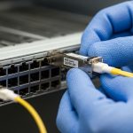
In day two operations, the hardest part of deploying SFP+ 10 gigabit links is not buying optics, it is matching the module type to the cabling plant, switch vendor behavior, and optics diagnostics so the link stays up during maintenance windows. This article helps network engineers and field techs compare fiber transceivers versus DAC and active copper, with concrete specs, failure modes, and a selection checklist for fast PMF-style validation. You will also get a decision matrix to reduce rework when procurement and cabling are already locked.
Fiber SFP+ 10 gigabit vs DAC vs active copper: performance reality check

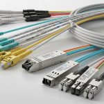
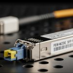
All three options can carry 10GBASE traffic, but they differ sharply in reach, signal integrity sensitivity, and how they behave under temperature and link training. Fiber SFP+ modules (typically 850 nm multimode or 1310 nm single mode) are distance-friendly and usually stable over longer runs. DAC (direct attach copper) is simplest for short distances like within a rack, while active copper extends reach beyond what passive DAC tolerates. In practice, engineers select based on the installed fiber or copper reach budget first, then verify switch compatibility and diagnostics.
Typical link targets you will actually see
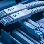
Common enterprise goals include: ToR-to-aggregation within the same row (short copper or DAC), leaf-to-spine across a data hall (often fiber), and server-to-switch uplinks (DAC or SR fiber depending on cabling). For fiber, 10GBASE-SR is widely deployed with 850 nm optics over OM3/OM4 multimode; 10GBASE-LR uses 1310 nm single mode for longer reach. For copper, cabling quality and connector cleanliness dominate outcomes faster than raw module specs.
Technical specifications comparison
Use the table below as a first-pass filter before checking your exact switch transceiver list and optics vendor datasheets.
| Option | Typical standard | Wavelength / medium | Reach (typical) | Connector | Power (typical) | Operating temperature | DOM support |
|---|---|---|---|---|---|---|---|
| Fiber SR SFP+ | 10GBASE-SR | 850 nm MMF | Up to 300 m OM3, 400 m OM4 | LC | ~0.8–1.5 W | 0 to 70 C (varies by vendor) | Often yes (per SFP MSA) |
| Fiber LR SFP+ | 10GBASE-LR | 1310 nm SMF | Up to 10 km | LC | ~0.9–2.0 W | -5 to 70 C (varies) | Often yes |
| DAC SFP+ | 10GBASE-CU | Passive copper | ~3–7 m (depends on cable) | SFP+ plug | ~0.5–1.0 W | 0 to 70 C | Sometimes (many support DOM) |
| Active copper SFP+ | 10GBASE-CU / vendor extension | Active copper | ~10–30 m (varies) | SFP+ plug | ~1.5–3.0 W | 0 to 70 C | Often yes |
Field note: the reach values above assume correct fiber grade (OM3 vs OM4), clean LC endfaces, and cabling within vendor link budgets. Always validate with your switch vendor’s transceiver compatibility guidance and the vendor datasheet for the exact part number. For standards context, IEEE 802.3 defines the 10GBASE families; SFP module behavior follows SFP Multi-Source Agreement (SFP MSA). Source: IEEE 802.3 Source: SFP MSA ecosystem references via SNIA
Pro Tip: If a link flaps only under load after a cold start, do not chase packet loss first. Pull the DOM readings (Tx power, Rx power, and temperature) and compare them to the vendor’s recommended thresholds; a marginal connector polish or slightly over-attenuated fiber can pass link training but fail BER under higher transmit duty cycles.
Compatibility and DOM: how switches really behave with SFP+ 10 gigabit modules
Switch ports often enforce transceiver requirements beyond basic link capability, including vendor-coded EEPROM identifiers and acceptable optical power ranges. Many enterprise switches also use Digital Optical Monitoring (DOM) values for alarms; if a third-party module reports DOM in an unexpected format or with out-of-range thresholds, you can see “link up” yet fail monitoring policies. Before deploying, verify the switch model’s documented compatibility list and plan a quick staging test with your exact module SKU.
What to check during validation
On the switch CLI, confirm that the port reports the expected DOM fields (at minimum: receive power, transmit power, temperature, and bias current). Then record baseline values at idle and during a traffic burst. If the module does not support DOM, some platforms still operate the link but will mark the transceiver as “unsupported” for monitoring and may block certain automation workflows.
Concrete module examples you can benchmark
Engineers commonly deploy known-good SKUs such as Finisar-compatible optics (for example, FTLX8571D3BCL class parts for 10GBASE-SR), Cisco-branded optics (for example, Cisco SFP-10G-SR class parts), and widely used third-party options from FS.com (for example, SFP-10GSR-85 class). Your exact ordering part number matters because vendors sometimes ship multiple revisions with different DOM calibration. Always cross-check the vendor datasheet for optical parameters and the switch’s transceiver support notes. Source: Cisco transceiver documentation Source: Finisar transceiver datasheets Source: FS.com transceiver specifications
Cost and ROI: what you save, what you risk, and how TCO changes
On paper, third-party optics are cheaper per module, but the real ROI depends on failure rate, warranty terms, and how much engineer time you spend re-seating and validating ports. A typical SFP+ 10 gigabit SR fiber module might cost less than OEM parts, but your total cost includes downtime risk and troubleshooting time when DOM or EEPROM identifiers do not match your automation expectations. For copper DAC, the trade is usually lower power and faster install, but cable length limits force re-cabling if the planned reach is wrong.
Realistic price bands and TCO factors
In many enterprise procurement cycles, OEM optics can price materially higher than third-party equivalents, while still offering robust compatibility documentation. Budget for: module cost, spares, labor for staged testing, and the operational overhead of monitoring mismatches. If you run high-volume ports (for example, 48 ToR switches), even a small per-port failure probability can dominate annual TCO when you factor truck rolls and change windows.
- Fiber SR SFP+: often low to mid tens of USD per module depending on brand and DOM behavior.
- Fiber LR SFP+: often higher due to single-mode optics and tighter link budget requirements.
- DAC: usually cheapest per port for short reach, but only if your cable plant matches the intended length.
- Active copper: mid-range cost, higher power draw, and more sensitivity to cable quality than passive DAC.
Limitation honesty: cheaper modules can work, but your risk is higher if you do not run a staging test on the exact switch model and firmware. Vendor lock-in is real in monitoring and automation, not only in link capability. For cost planning, treat optics as a software dependency for hardware: validate once, then standardize.
Deployment scenario: choosing the right SFP+ 10 gigabit option in a leaf-spine build
Consider a 3-tier data center leaf-spine topology with 48-port 10G ToR switches and 2 spine pairs. Each leaf has 24 server-facing 10G links using DAC for same-rack server uplinks (typical 3 m runs), while leaf uplinks use fiber SR for within-row aggregation to spine (typical 120 m across structured cabling). For cross-row links that exceed multimode reach or where OM3 is not available, the team uses LR over single-mode with 1310 nm optics for up to 10 km where needed. During staging, the team verifies DOM thresholds and records baseline Rx power; later, during a maintenance window, they validate that link re-trains cleanly after a planned port reset.
Fast validation approach that avoids rework
In a pilot, deploy a small batch matching each link class: 10GBASE-SR for OM3/OM4 runs, DAC for short server uplinks, and LR for longer or single-mode-required paths. Run traffic for at least one diurnal cycle and monitor BER proxies (if available), interface counters, and DOM alarms. Only then scale procurement to the full fleet.
Selection criteria checklist: pick the module type before you pick the vendor
Engineers optimize for reliability and speed, not brand loyalty. Use this ordered checklist during each rollout to keep validation tight and avoid “it links but it breaks” surprises.
- Distance: measure installed run length and account for patch cords, couplers, and expected attenuation.
- Medium and cabling grade: confirm OM3 vs OM4 for SR; confirm single-mode fiber type and connector loss for LR.
- Switch compatibility: check the switch transceiver compatibility list and firmware notes for your exact model.
- DOM and monitoring requirements: ensure DOM fields populate correctly for your alerting and automation.
- Operating temperature: validate ambient conditions near the port and ensure the module’s spec covers your environment.
- Budget and spares strategy: compare unit cost plus spare inventory and warranty terms.
- Vendor lock-in risk: decide whether you can standardize on one ecosystem or need a multi-vendor qualification path.
Common mistakes and troubleshooting tips for SFP+ 10 gigabit links
Most outages are preventable with disciplined optics handling, correct reach math, and switch-level validation. Below are concrete failure modes we have seen in the field, with root cause and remediation.
Link comes up, then errors spike under load
Root cause: marginal fiber endface cleanliness or slightly over-attenuated link budget causing elevated BER at higher throughput. Sometimes connectors look “fine” but have micro-scratches that worsen with time.
Solution: clean LC connectors with proper wipes and inspect with a fiber microscope; re-terminate or replace patch cords if needed. Re-measure with an optical power meter and compare Rx power to the module datasheet expectations.
Port shows “unsupported transceiver” or DOM alarms
Root cause: EEPROM identifier or DOM calibration mismatch with the switch’s expected transceiver profile, especially with certain third-party modules or incorrect part revisions.
Solution: deploy only modules validated on your switch model and firmware. If you must mix vendors, run a staged test and confirm your monitoring stack handles missing or differently scaled DOM values.
Works in staging, fails in the cabinet after thermal cycling
Root cause: module temperature operating range mismatch or airflow differences between staging racks and production enclosures. Some modules are rated up to 70 C, but cabinet hotspots can exceed what you assumed.
Solution: verify airflow and measure inlet air temperature; add or adjust baffles if needed. Keep spare modules with the same temperature grade, and consider higher-spec optics if the environment is harsh.
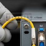
Copper DAC length mismatch or poor bend radius
Root cause: deploying a DAC near its maximum length or routing it with too tight bends, degrading signal integrity and causing intermittent link drops.
Solution: replace with the correct length category and route with proper bend radius. Confirm link stability with a traffic test that matches real load and monitor interface counters over time.
Decision matrix: which SFP+ 10 gigabit option fits your constraints
Use this matrix to choose quickly when you have mixed cabling and tight change windows.
| Your constraint | Best default | Why | Watch-outs |
|---|---|---|---|
| Short reach inside a rack (about 3 m) | DAC SFP+ | Fast install, fewer connectors, low power | Length is fixed; ensure switch supports DAC types |
| Structured cabling with OM3/OM4 | Fiber SR SFP+ | Predictable link budgets for 850 nm MMF | Connector cleanliness and fiber grade validation |
| Longer runs or mixed plant without MMF reach | Fiber LR SFP+ | 1310 nm SMF supports up to 10 km | Single-mode optics and patch loss must be controlled |
| Copper runs longer than passive DAC | Active copper | Extends reach beyond passive limits | Higher power draw; more sensitivity to cable quality |
| Strict monitoring and automation | Validated fiber or DAC with DOM | Consistent DOM behavior reduces false alarms | Qualify part revisions per switch firmware |
Which option should you choose?
If you have short server uplinks within a rack and you can lock the exact cable length, choose DAC SFP+ for speed and simplicity. If you are deploying across structured cabling with known OM3 or OM4, pick fiber SR SFP+ because it scales cleanly and avoids copper signal integrity headaches. If you face long distances, uncertain multimode reach, or single-mode plant, choose fiber LR SFP+ and validate patch loss with optical measurements. For copper runs that exceed passive DAC capability but cannot be converted to fiber, select active copper and run a staging test that includes thermal cycling and sustained traffic.
Next step: build a small “transceiver qualification kit” in your lab, then standardize one validated SKU per link class using transceiver-qualification-for-enterprise-10g as your rollout template.
FAQ
What does SFP+ 10 gigabit mean in practice?
It refers to the SFP+ form factor carrying 10G data rates, typically for 10GBASE-SR, 10GBASE-LR, or 10GBASE-CU variants. The key is the module type and medium: fiber SR/LR or copper DAC/active copper.
Can I mix fiber SR and LR on the same switch?
Yes, as long as each port is configured for the correct optics type and your switch supports the transceiver profile. Do not assume reach behavior; SR and LR use different wavelengths and require different fiber plants.
Do I need DOM for SFP+ 10 gigabit optics?
If you rely on alarms, capacity planning, or automated remediation, DOM is strongly recommended. Some modules link without DOM, but monitoring tools may mark them as unsupported or fail to collect useful thresholds.
Why do I get “link up” but no traffic?
Common causes include VLAN or L2 configuration mismatch, duplex and speed negotiation issues on the far end, or optics that pass link training but have excessive errors. Check interface counters, optics DOM values, and confirm the