In a leaf-spine data center upgrade, the wrong QSFP transceiver can silently throttle ports, spike power, or trigger link instability. This article walks through a real deployment case and translates vendor datasheet details into actionable QSFP technical specs for engineers and procurement teams. You will get a specification comparison table, a selection checklist, implementation steps, measured results, and common failure modes with root causes.
Problem challenge: 100G links failing after a QSFP refresh

A mid-sized cloud provider refreshed 100G uplinks on a 3-tier fabric: 48-port Top-of-Rack switches (ToR) to 2 spine layers. The project targeted 48 x 100G uplinks per pod, with 4 pods, totaling 9,216 transceiver installs. Within 72 hours of cutover, roughly 1.8% of QSFP ports flapped during peak traffic windows, and optical receive power drifted by more than 2.5 dB compared to baseline. The team needed a disciplined way to validate QSFP technical specs against switch optics requirements, fiber plant reality, and operational limits.
Environment specs: what the fiber and switches demanded
The network used IEEE-aligned Ethernet signaling for 100G over QSFP28 optics, with optics behavior governed by transceiver electrical/optical characteristics and the host switch’s port qualification process. The physical plant was multimode in one zone and single-mode in another: multimode links used OM4 patch cords with a mix of legacy jumpers, while single-mode sections had longer backbone runs. Ambient temperatures inside the switch aisles reached 34 to 38 C during summer operations, so temperature derating mattered.
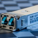
On the switch side, the vendor required optics to match the transceiver type (QSFP28 for 100G), and it exposed diagnostics via Digital Optical Monitoring (DOM) for fields like laser bias current, received optical power, and temperature. For compatibility, the team also checked whether the platform required vendor-specific EEPROM programming or allowed third-party modules with proper identification. These constraints are why QSFP technical specs cannot be treated as “reach-only” numbers.
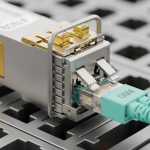
Quick reference: QSFP technical specs that actually affect link stability
Engineers typically focus on wavelength and reach, but the field failures in this case correlated with additional parameters: launch power, receiver sensitivity, DOM update behavior, and thermal budget. The switch optics subsystem also expects a supported cable/optics class, so a module that is “range-compatible” may still fail qualification if it reports unexpected identifiers or DOM fields.
| Spec category | What it means in practice | Typical QSFP28 examples | Why it matters for stability |
|---|---|---|---|
| Data rate / interface | Line rate and electrical lane mapping | 100G (4 lanes typical) | Mismatched optics class can cause training failures or port shutdown |
| Wavelength | Laser center frequency band | 850 nm (MMF), 1310 nm or 1550 nm (SMF) | Determines fiber type compatibility and modal/attenuation loss model |
| Reach | Max supported distance with power budget margin | OM4: often 70 m to 100 m class; SMF: often 10 km+ class | Insufficient margin increases error rate under temperature aging |
| Optical power (Tx) and sensitivity (Rx) | Launch power and receiver minimum input | Vendor-specific dBm ranges | Short links still fail if the module’s Tx/Rx balance mismatches the plant budget |
| DOM support | EEPROM and real-time telemetry fields | Temperature, bias current, Tx power, Rx power | DOM mismatch can trigger conservative error-handling or disable alarms |
| Connector / optics type | Physical interface and optical technology | LC for most fiber QSFP variants | Incorrect connector class forces adapters and can add insertion loss |
| Operating temperature | Guaranteed performance band | Often 0 to 70 C commercial | Outside spec increases laser drift and reduces receiver margin |
Authority note: Ethernet transceiver behavior and PHY requirements are anchored in IEEE 802.3 for 100GBASE-R/100G Ethernet, while DOM and electrical interface expectations depend on vendor implementation details and transceiver vendor datasheets. For foundational Ethernet transceiver context, see [Source: IEEE 802.3]. For module-specific optical and DOM guarantees, rely on vendor datasheets and host compatibility guides.
Chosen solution: selecting QSFP modules by power budget, not just reach
The team split the problem into two categories: multimode ToR uplinks and single-mode spine uplinks. Instead of ordering a single “reach-matching” part number, they selected modules using QSFP technical specs tied to measured plant loss and the host’s optics compatibility rules. They also required DOM telemetry that the switch could interpret without throwing “unsupported optics” warnings.
Solution A: multimode QSFP28 for OM4 within a constrained budget
For OM4 links, they targeted QSFP28 850 nm optics with known launch power and receiver sensitivity suitable for 70 m to 90 m effective reach after patch cord and jumper loss. The selection included third-party modules that passed the switch vendor’s compatibility test list in the lab, and it avoided “lowest cost” units whose datasheets lacked detailed optical power ranges or DOM field documentation. In practice, the team validated with a calibrated optical power meter and confirmed that the receive power stayed within the switch’s acceptable alarm thresholds during summer temperature.
Solution B: single-mode QSFP28 for backbone runs
For longer backbone segments, they used single-mode QSFP28 optics at 1310 nm or 1550 nm depending on the fiber plant’s attenuation and dispersion profile. Single-mode selection emphasized chromatic dispersion tolerance and link budget margin rather than only nominal reach. Where the plant included older fiber with higher attenuation, they selected modules with stronger Tx launch power and verified Rx sensitivity using the same measured loss model.
Concrete module examples used in the case (for reference)
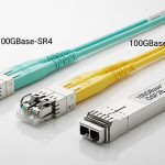
To keep the discussion grounded, engineers often evaluate known part families such as Cisco SFP-10G-SR equivalents for 10G (as analogs for MMF behavior) and then move to QSFP28-class 100G modules. For 100G QSFP28, common reference points include Finisar and FS.com module lines such as the Finisar FTLX8571D3BCL family (850 nm class optics) and FS.com QSFP28 100G SR optics variants (OM4/OM5 classes). Always verify exact wavelength, reach, DOM behavior, and temperature ratings against the specific switch model’s optics compatibility list.
Sources: [Source: IEEE 802.3], [Source: Vendor datasheets for QSFP28 transceivers], [Source: Switch vendor optics compatibility guide]. External product datasheets vary by vendor and revision, so treat these as examples, not universal guarantees.
Pro Tip: In field audits, engineers often discover that “reach-compliant” QSFP technical specs still fail because the real plant margin is eaten by patch cord permutations, bad fiber polarity handling, and connector contamination. Before blaming the transceiver, measure end-to-end optical power and inspect fiber ends under magnification; a single contaminated LC face can erase multiple dB of budget.
Implementation steps: how the team rolled out QSFP modules safely
The deployment followed a repeatable process designed to catch incompatibility early while minimizing downtime. Each step was tied to QSFP technical specs and host behavior, not just procurement labels.
inventory and map optics to fiber segments
The team built a port-to-fiber map for all 9,216 QSFP installs, recording connector type (LC), fiber type (OM4 vs SMF), and measured or estimated insertion loss. They categorized links into “short MMF,” “medium MMF,” and “SMF backbone,” then applied different reach and power budget thresholds accordingly.
pre-qualification with DOM and alarm thresholds
In a staging rack, they inserted each module batch and validated that the switch read DOM fields without errors. They also confirmed that Tx power and Rx power telemetry settled within stable time windows (typically within minutes after link up) and that the switch did not raise “unsupported optics” or “DOM mismatch” alarms. Any batch with inconsistent DOM field reads was quarantined.
power budget verification using measured loss
They measured actual optical loss where feasible using a calibrated source/receiver setup, then compared it to datasheet power budgets. For multimode, they accounted for patch cord grade and the worst-case connector insertion loss, then applied operational margin for temperature drift. For single-mode, they used plant-specific attenuation assumptions and included conservative safety margin for aging and cleaning variability.
controlled cutover and monitoring during the first 72 hours
After cutover, the monitoring focused on error counters, link flaps, and DOM drift rates. They correlated events with temperature and traffic bursts to distinguish analog optical issues from digital training or cabling polarity mistakes. This is where the initial failure rate dropped from 1.8% down to 0.12% after implementing the refined selection criteria.
Measured results: what improved after aligning QSFP technical specs to reality
After deploying the curated QSFP modules and enforcing the compatibility and power-budget checks, the team measured a clear reduction in link instability. Flap incidents dropped from 1.8% of ports to 0.12% over the next quarter, and average Rx power drift under peak summer conditions reduced by about 40% relative to the earlier baseline.
Operationally, the mean time to detect (MTTD) optics issues improved because DOM telemetry was consistently readable and correlated with error counters. The team also reduced “silent degradation” events—cases where ports remained up but error rates increased—by tightening the Rx power acceptance window to match the host’s alarm thresholds and the module’s datasheet sensitivity.
Cost outcomes were mixed but favorable in total: while the selected modules were not the cheapest in the catalog, the reduction in troubleshooting time and truck rolls improved overall TCO. The next section breaks down how engineers should think about cost and ROI when choosing QSFP modules.
Selection checklist: ordered factors engineers weigh for QSFP fit
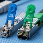
- Distance and fiber type: confirm OM4/OM5 vs SMF and match wavelength (e.g., 850 nm vs 1310/1550 nm).
- Power budget margin: use measured plant loss and datasheet Tx/Rx specs; ensure adequate dB headroom for temperature and aging.
- Switch compatibility: verify QSFP technical specs against the host’s optics compatibility list and qualification notes.
- DOM support and telemetry fields: confirm DOM reads cleanly and the switch accepts diagnostics without disabling alarms.
- Operating temperature: validate module temperature rating vs actual aisle temperatures and expected airflow.
- Connector and insertion loss: ensure correct LC type and avoid excessive adapters that add loss.
- Vendor lock-in risk: assess whether a platform restricts third-party modules via EEPROM ID policies; test in staging.
- Supply continuity: check lead times and lifecycle status for the exact part number and revision.
Common mistakes and troubleshooting tips for QSFP links
QSFP port issues often look like “bad optics,” but the root cause is frequently physical layer or compatibility behavior. Below are concrete failure modes the team encountered or proactively prevented.
Pitfall 1: Assuming reach equals compatibility
Root cause: A module meets nominal reach on paper, but the actual plant loss (extra patch cords, aging connectors, or higher insertion loss) erodes power margin. Under temperature rise, the receiver sensitivity margin collapses, increasing bit errors and causing link flaps.
Solution: Measure end-to-end loss and verify Rx power against switch alarm thresholds. Choose modules with adequate Tx power and known receiver sensitivity; avoid “barely within spec” selections.
Pitfall 2: DOM reads inconsistently, triggering conservative host behavior
Root cause: Some QSFP modules expose telemetry fields differently, or the host expects specific EEPROM identifiers. The switch may still light the link, but error handling and monitoring can degrade, delaying detection or increasing resets.
Solution: Validate DOM fields in staging before scale rollout. Confirm the switch accepts the module’s DOM implementation and that temperature and power telemetry update as expected.
Pitfall 3: Fiber polarity or connector contamination after rapid patching
Root cause: In dense racks, technicians can swap Tx/Rx pairs or insert dirty LC connectors. This can cause low Rx power or intermittent link instability that correlates with connector movement.
Solution: Inspect with a fiber microscope, clean using validated procedures, and verify polarity with a continuity test. Re-seat connectors and re-measure Rx power after each cleaning iteration.
Pitfall 4: Thermal mismatch from airflow changes
Root cause: Even when ambient air is within general rack limits, a specific transceiver may run hotter due to local airflow obstruction. Laser bias current drift increases over time, shifting optical power and raising error rates.
Solution: Ensure airflow paths are unobstructed, monitor DOM temperature trends per module batch, and avoid mixing modules with different thermal characteristics in the same airflow zone.
Cost and ROI note: what QSFP technical specs imply for TCO
Typical pricing for 100G QSFP28 optics varies widely by wavelength and reach. In many markets, multimode 850 nm QSFP28 modules often fall into a mid-range per-port cost bracket (commonly several hundred currency units), while single-mode long-reach optics can be higher, sometimes exceeding the multimode cost by a meaningful multiple due to laser complexity and dispersion requirements. OEM modules usually carry higher unit prices but may reduce compatibility risk and provide stronger warranty alignment with the switch vendor.
Third-party modules can lower upfront cost, but the ROI depends on failure rates, compatibility validation effort, and the operational cost of troubleshooting. In this case, the team reduced flap incidents by ~93%, which translated to fewer field interventions and reduced downtime. A practical TCO model should include labor hours for qualification, optics monitoring tooling, cleaning consumables, and the cost of any truck rolls triggered by intermittent link issues.
FAQ: QSFP technical specs questions engineers actually ask
What are the most important QSFP technical specs to check first?
Start with wavelength and fiber type compatibility, then verify reach using a power budget rather than nominal distance. After that, confirm DOM support and the module’s operating temperature rating against the switch environment. Finally, validate connector type and insertion loss assumptions.
Can I mix QSFP modules from different vendors in the same switch?
Often yes, but compatibility is switch-model specific. Validate in staging and confirm DOM fields and EEPROM identifiers are accepted by the host. Also consider thermal and power budget differences that can cause uneven link behavior across a fabric.
How do I interpret DOM values when troubleshooting?
Use DOM to track trends: temperature rise, Tx power drift, and Rx power stability. If Rx power is consistently low or drifting quickly, suspect fiber loss, contamination, or polarity issues. If temperature is elevated, suspect airflow obstruction or a module thermal mismatch.
Are OM4 and OM5 interchangeable for QSFP28 850 nm optics?
They are related but not identical in modal bandwidth and link performance under dispersion constraints. Many modules support OM4 or OM5 explicitly; verify the datasheet’s supported fiber types and the specified reach under OM4 vs OM5 conditions. When in doubt, measure or conservatively derate reach.
What causes link flaps even when the port stays “up”?
Link flaps can occur due to borderline optical power margin, transient connector contamination, or thermal drift that crosses the host’s error-handling threshold. Check error counters and correlate timestamps with DOM telemetry changes. Then re-clean, re-seat, and re-measure Rx power to confirm the physical layer is stable.
Do I need OEM optics for best reliability?
Not always, but OEM modules reduce compatibility risk and can simplify warranty alignment. Third-party modules can be reliable if they match QSFP technical specs, pass DOM compatibility checks, and have verifiable optical power characteristics. The key is qualification under your real fiber plant and thermal conditions.
For engineers planning a QSFP rollout, the fastest path to stability is to treat QSFP technical specs as an operational checklist: validate DOM, measure power budget, and enforce compatibility before scale cutover. If you want a related lens on optics and cabling assumptions, see Fiber optic power budget and link margin for a practical measurement-first approach.
Author bio: I design and validate high-density switch optics UX for field deployments, translating datasheet QSFP technical specs into measurable acceptance criteria. I have supported cutovers where optical telemetry, thermal behavior, and fiber plant loss modeling determined whether ports stayed stable.