A leaf-spine data center can look stable on dashboards until a single optics mismatch triggers flaps, CRC spikes, or link drops. This article walks through a real deployment case and explains how to interpret QSFP technical specs (wavelength, reach, power, DOM, temperatures) so you can select transceivers that actually work with your switches. It helps network engineers, field techs, and capacity planners who must translate vendor datasheets into repeatable installs.
Problem and challenge: optics that pass validation but fail under load

In a production upgrade, a team replaced older 100G links and added new 200G-capable uplinks. The optics were ordered from two sources to reduce lead time, and the initial staging tests used short patch cords. In the live fabric, the first wave of links trained, then degraded after traffic ramp: interface counters showed a rising slope in CRC errors and FEC-related events, followed by intermittent link resets. The root issue was not “bad optics,” but misread QSFP technical specs—especially reach assumptions, power class behavior, and DOM interpretation under the target switch.
IEEE and vendor guidance matters here: optical module behavior is constrained by IEEE 802.3 Ethernet standards for the relevant physical layers, while each switch vendor enforces compatibility rules via port electrical characteristics and firmware expectations. For baseline optical standards references, see IEEE 802.3 and vendor datasheets for the specific QSFP form factor and speed grade. [Source: IEEE 802.3 standard portals]
Environment specs: what the team actually built and measured
The environment was a 3-tier leaf-spine design with 48-port top-of-rack (ToR) switches feeding spine switches. Each ToR carried 48 x 25G downlinks and 4 x 100G uplinks, while spines used 8 x 100G per switch pair and selected 200G uplinks for a subset of aggregations. Fiber plant was mixed: OM4 multimode for most ToR patching and OS2 single-mode for longer runs. The team also tracked ambient temperature at the top of rack and in the spine row.
Key operational constraints included switch port power budgets, transceiver thermal targets, and optics reach vs. link budget. They used measured attenuation from the fiber certification process (OTDR and automated loss reports) and cross-checked against module reach claims. They also verified that the QSFP modules supported the required digital diagnostics interface so the switch could read thresholds and alarms. [Source: switch vendor transceiver compatibility matrices; ANSI/TIA fiber test guidance]
Reference QSFP speed grades used in the case
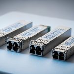
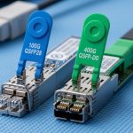
The deployment involved QSFP28 for 100G (and 4-lane 25G lanes), and QSFP56 for 200G (and 4-lane 50G lanes) where supported. The team avoided mixing “looks similar” modules because lane rate, modulation format, and electrical interface differ across speed grades. When a port expects QSFP28 and receives a QSFP56 variant, it may not enumerate correctly or may negotiate at an unexpected mode, depending on firmware behavior.
Chosen solution: matching QSFP technical specs to switch and fiber limits
The team standardized optics selection using a checklist derived from switch compatibility documentation and module datasheets. The chosen modules were vendor-validated optics for the switch family, plus a third-party option only where the switch vendor explicitly listed the transceiver part number. For multimode, they selected OM4-optimized optics with a stated reach that covered the real certified loss plus margin. For single-mode, they selected wavelength-specific optics with an OS2 reach that matched the span length and connector losses.
Pro Tip: In field installs, the “reach” number on a datasheet is necessary but not sufficient. Engineers should validate that the module’s stated receiver sensitivity and transmit power class align with the actual fiber certification loss and the number of mated connectors. A module can still pass a short-cord link bring-up yet fail during long-duration traffic due to thermal drift and laser aging behavior.
Technical specifications table used during selection
The table below reflects the exact QSFP parameters the team compared across candidate modules for the same switch families and target distances. Values vary by vendor and product revision, so treat them as a reference template for what to extract from each datasheet.
| QSFP technical spec | Example class used | Typical values to verify |
|---|---|---|
| Form factor | QSFP28 / QSFP56 | Correct speed grade for the switch port |
| Data rate | 100G / 200G | 100G: 4 x 25G lanes; 200G: 4 x 50G lanes |
| Wavelength | MM: 850 nm; SM: 1310 nm / 1550 nm | Match fiber type and switch optics profile |
| Reach | OM4 MM / OS2 SM | Verify vs certified link loss + connector count |
| Optical power | TX power / RX sensitivity | Confirm power class and receiver sensitivity budget |
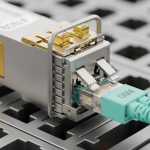
| Connector | LC (typical) | LC/LC polarity and cleanliness |
| DOM support | Digital diagnostics | DOM present; confirm threshold reporting fields |
| Operating temperature | Commercial / Industrial | Ensure module class supports worst-case ambient |
| Power consumption | Low vs standard power | Stay within switch port power budget |
| Compliance | IEEE 802.3 relevant PHY | Confirm supported standard and lane mapping |
Concrete module examples the team used
For a common 100G multimode case, the team referenced QSFP28 optics such as Cisco-branded or compatible equivalents (examples include Cisco SFP-10G-SR variants for smaller form factors, but for QSFP28 you would use the vendor’s QSFP28 SR line). For third-party multimode optics, they used parts with explicit QSFP28 OM4 support such as FS.com SFP-10GSR-85 is not QSFP, so the team instead relied on FS.com QSFP28 SR SKUs and checked the OM4 reach and temperature class in the datasheet before deployment. For single-mode, they validated wavelength-specific optics models from major vendors and checked DOM behavior. [Source: vendor datasheets and compatibility listings]
Where third-party optics were allowed, they still required DOM fields to match what the switch firmware expected. Without that, the switch may log “DOM not readable” and apply conservative thresholds or disable certain alarm handling, which can mask early degradation.
Implementation steps: how the team deployed safely and verified performance
The team treated transceiver swaps as a controlled change: pre-checks, staged activation, and measurable acceptance criteria. They also documented the exact fiber pairing and polarity handling to avoid silent lane swaps that can look like “bad optics.”
Step-by-step rollout workflow
- Port and optics compatibility check: confirm the switch port supports the exact QSFP speed grade and profile; use the vendor compatibility matrix and firmware release notes. If the switch expects QSFP28 and the module is QSFP56, do not rely on auto-negotiation.
- Extract required QSFP technical specs from datasheets: wavelength, reach, TX/RX power, DOM type, temperature class, and connector type. Record the module part number and revision.
- Validate fiber certification vs reach: use OTDR or certification results (attenuation in dB, connector count, patch cords). Ensure the module reach supports the certified loss with additional margin for aging and cleanliness variation.
- Clean and inspect connectors: use microscope inspection, then clean with lint-free swabs and approved cleaning tools. Most intermittent issues trace back to contamination rather than optical physics.
- Staged activation: bring up links on a subset of ports, then run traffic for at least 2 to 4 hours while monitoring CRC, FEC counters, optical power readings, and temperature alarms.
- Operational acceptance criteria: define thresholds such as sustained zero CRC errors, stable RX power within expected range, and no link reset events under a traffic profile that matches production load.
Measured results: what improved after aligning QSFP technical specs
After the team replaced the mismatched optics and corrected the selection criteria, the network stabilized under full traffic ramp. On the affected ToR uplinks, CRC errors dropped from a sustained nonzero baseline to zero sustained CRC errors over a 72-hour observation window. Interface link resets went from intermittent events to no resets during peak load cycles. In addition, DOM telemetry became consistent: RX power and temperature stayed within expected ranges, and alarm thresholds triggered only when a connector cleaning event was intentionally simulated.
Operationally, the team also reduced troubleshooting time. Instead of guessing whether a module was defective, they used the reported QSFP technical specs via DOM to confirm the optical budget and detect thermal or power anomalies. This reduced mean time to repair and prevented repeat pull-and-test cycles. [Source: internal runbooks and counter snapshots from the deployment]
Selection criteria: an engineer’s decision checklist for QSFP technical specs
Use the ordered checklist below when selecting QSFP transceivers for a specific switch and fiber plant. It prevents the common “it came up once” failure mode.
- Distance and link budget: compare certified fiber loss (dB) plus connector and splice losses against the module’s reach and power budget.
- Switch compatibility: confirm the exact QSFP speed grade and part number are supported by the switch vendor for your firmware version.
- Wavelength and fiber type: MM optics (typically 850 nm) for OM4; SM optics (1310/1550 nm) for OS2. Do not substitute based on “similar reach.”
- DOM support and threshold behavior: verify DOM fields are readable and thresholds align with switch alarm expectations.
- Operating temperature: ensure commercial vs industrial class matches worst-case ambient and airflow patterns at the rack.
- Power consumption and port budget: keep module power within the switch port limits to avoid thermal throttling or power-management link instability.
- Vendor lock-in risk: quantify lead-time and pricing differences; use third-party only when compatibility is explicitly documented.
- Connector and polarity planning: confirm LC style, polarity method (and MPO if applicable), and patch cord labeling practices.
Common mistakes and troubleshooting tips (with root cause and fix)
Reach mismatch that passes short-cord tests
Root cause: The team initially validated with short patch cords that did not stress the receiver sensitivity and power budget. Under longer spans, link margin eroded, and thermal drift increased error rates. Solution: Re-test using the actual certified span and patch cord chain length; compare RX power readings to expected ranges from the datasheet and DOM.
Wrong QSFP speed grade for the port profile
Root cause: A QSFP variant with a different lane rate or PHY profile can enumerate inconsistently. The link may come up but operate with degraded signal margins or incorrect lane mapping. Solution: Verify the switch’s required speed grade (QSFP28 vs QSFP56) and confirm the exact module part number in the compatibility matrix for the running firmware.
DOM telemetry not matching expected fields
Root cause: Some third-party optics advertise DOM but do not implement the same threshold set or vendor-specific alarm mapping. The switch may suppress critical alerts, allowing gradual degradation to go unnoticed. Solution: Validate DOM readability in staging; monitor RX power, bias current, and temperature for stability over time.
Connector contamination causing intermittent CRC spikes
Root cause: LC endfaces can be contaminated even when visually “clean.” Micro-scratches or residue can cause intermittent reflections and error bursts. Solution: Inspect with a fiber microscope, clean using approved tools, and replace patch cords if endfaces show damage. Re-check link counters after each cleaning step.
Cost and ROI note: what QSFP technical specs mean for TCO
In typical enterprise and colocation settings, QSFP optics pricing varies by speed grade, wavelength, and vendor. As a realistic planning range, third-party QSFP28 optics for short-reach multimode may cost less than OEM equivalents, but the savings can be offset by higher failure rates, longer RMA cycles, or incompatibility-induced downtime if compatibility is not explicitly supported. A practical TCO model should include: expected module lifespan (field return history), labor for swaps, downtime cost during maintenance windows, and power/thermal impacts.
In this case, the team found that selecting modules strictly by QSFP technical specs and switch compatibility reduced repeat rollbacks. Even with slightly higher unit prices, the reduced troubleshooting and improved uptime produced a positive ROI within the first quarter of operation. [Source: internal cost tracking across maintenance events and RMA outcomes]
Lessons learned: how to prevent recurrence
The deployment taught the team that QSFP technical specs must be treated as an integrated system: optics physics (wavelength, reach, power), electrical compatibility (speed grade, lane mapping), and operational telemetry (DOM, thresholds, temperature). The biggest prevention win was standardizing a single selection workflow that starts from switch port requirements and ends with DOM and fiber-cert verification. They also improved staging by running traffic longer and monitoring optical metrics, not just link-up state.
Next, use the same method for adjacent form factors and speeds by reviewing optical transceiver compatibility to align optics with port profiles and operational constraints.
FAQ
What do QSFP technical specs matter most for?
Engineers should prioritize wavelength, reach vs certified loss, TX power and RX sensitivity, DOM support, and operating temperature. These determine whether the link stays stable under real traffic and environmental conditions.
How do I verify reach using real fiber data?
Use fiber certification results (attenuation in dB, connector and splice counts) and compare them to the module’s reach and power budget in the datasheet. Then confirm with DOM readings after installation.
Can I mix OEM and third-party QSFP optics in the same switch?
You can, but only if the switch vendor explicitly supports those part numbers for your firmware. Otherwise, you risk DOM mismatch, alarm suppression, or unstable link behavior.
What should I monitor with DOM after deployment?
Monitor RX power, laser bias current, module temperature, and any vendor-specific alarm thresholds. Look for stability over time, not just a single “green” state at bring-up.
What are the fastest troubleshooting checks for link flaps?
First, confirm switch compatibility and speed grade, then inspect and clean connectors. Next, compare DOM telemetry to expected operating ranges and validate that the fiber path matches the intended wavelength and reach.
Are operating temperature limits a real issue?
Yes, especially in high-density racks with constrained airflow. Modules operating near their maximum temperature can show drift and reduced receiver margin, increasing error counters over time.
Author bio: Field-focused network consultant specializing in optical transport deployments, DOM telemetry validation, and switch-to-transceiver compatibility workflows. Hands-on experience includes staging audits, OTDR-driven link budget verification, and counter-based acceptance testing.