Hot-pluggable transceivers are supposed to be “swap and go,” but in real networks the first thing that breaks is often telemetry: DOM monitoring stops updating, alarms misfire, or the switch refuses the optics. This article helps network engineers and field techs verify DOM monitoring right after insertion, choose the right module for their topology, and troubleshoot the usual root causes. If you manage 10G/25G/100G links in a multi-vendor environment, you will leave with a practical checklist and a decision matrix.
DOM monitoring vs “it links up”: what you should validate

Link establishment only proves the physical layer can train and pass traffic; it does not prove the switch can reliably read Digital Optical Monitoring values. DOM typically exposes laser bias current, received optical power, transmit power, and temperature over a management interface inside the module (commonly via the MDIO/I2C style bus used by SFP-family and QSFP-family transceivers). In practice, you want to validate three things immediately after hot-plug: the switch sees the module in the expected form factor, the optics page shows sane thresholds, and alarms clear/track correctly under load.
Quick post-insertion validation steps
- Confirm module presence: check the switch transceiver inventory entry updates within a few seconds of insertion.
- Verify DOM monitoring fields: ensure temperature, Tx bias/current, Tx power, and Rx power populate (not “N/A” or zeroed values).
- Trigger a controlled optical check: run link traffic (for example, a 5 to 10 minute iperf3 stream) and watch Rx power stabilize rather than oscillate wildly.
- Validate thresholds and alarms: confirm the switch’s DOM thresholds match the module class; verify no persistent “over temp” or “laser bias out of range” alarms.
Pro Tip: In the field, “DOM monitoring works but alarms are noisy” is often not an optics problem. It is frequently a threshold mapping mismatch between the switch’s expected transceiver profile and the module’s DOM calibration constants, so the fix is sometimes upgrading switch firmware or selecting a module with the correct DOM profile rather than swapping optics repeatedly.
Head-to-head: SFP/SFP+ SR, LR, and ER modules for DOM monitoring reliability
For many teams, the real decision is not just distance—it is whether the switch will consistently read DOM monitoring values across module vendors and temperature swings. Below is a practical comparison for common SFP-family optical types you might deploy in access, aggregation, or leaf-spine fabrics. Values vary by vendor and exact part number, so treat the table as engineering guidance for what to verify, not a promise of identical behavior.
| Module type (example) | Wavelength | Typical reach | Connector | DOM monitoring expectation | Operating temperature | Common switch fit issue |
|---|---|---|---|---|---|---|
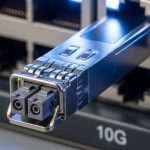
| SFP-10G-SR (Cisco SFP-10G-SR) | 850 nm | Up to 300 m (OM3) | LC | Tx bias, Tx power, Rx power, temp should populate | 0 to 70 C (typical class) | Thresholds tuned for specific vendor profile |
| SFP-10G-LR (common LR 1310 nm) | 1310 nm | Up to 10 km (SMF) | LC | DOM fields stable after warm-up | -40 to 85 C (many extended options) | DOM values may differ; alarms need calibration |
| SFP-25G-LR / SFP28 class LR (vendor example) | 1310 nm | Up to 10 km (SMF) | LC | More frequent monitoring polling on some platforms | Platform may require specific DOM support mode |
Standards context matters. The electrical interface for SFP/SFP+ optics aligns with IEEE 802.3 transceiver expectations, and DOM is standardized in the sense that vendors implement a common digital monitoring interface, but the exact calibration and threshold behavior can still vary. For deeper background on transceiver requirements, see [Source: IEEE 802.3]. For module form factor and management behavior details, consult vendor datasheets for the specific part you plan to deploy, such as [Source: Cisco SFP-10G-SR datasheet] or [Source: Finisar/FutureNet transceiver datasheets].
Compatibility reality check: DOM monitoring across vendors and switch models
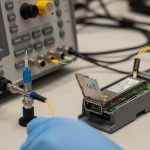
DOM monitoring reliability depends on more than the optics. Switch ASIC behavior, firmware, and the expected transceiver profile can make two “DOM-compatible” modules behave differently. Before you scale deployments, test in a lab with your exact switch models and software versions, then record the observed DOM field ranges for your operating envelope.
What engineers check for compatibility
- Form factor and electrical class: SFP vs SFP+ vs SFP28 vs QSFP28 are not interchangeable.
- DOM feature set: some modules expose additional diagnostics; some platforms only parse a subset.
- Digital ID and profile: the module’s identification bytes can influence threshold mapping and alarm logic.
- Firmware maturity: older switch firmware may misread non-OEM calibration constants.
- Link speed and FEC mode: for higher-speed optics, the switch may enforce FEC requirements that affect link stability and thus the quality of DOM trends.
If you are deploying third-party optics, pick models that are explicitly listed for your switch or that have documented DOM behavior. Examples you might see in the market include Cisco OEM optics like Cisco SFP-10G-SR, and third-party 10G SR optics such as Finisar FTLX8571D3BCL or FS.com SFP-10GSR-85. Even then, always validate in your exact chassis, because DOM monitoring behavior can differ by firmware.
Cost and ROI: OEM vs third-party with DOM monitoring in mind
Optics pricing is only part of total cost. The biggest ROI lever is operational time: how often you troubleshoot “link up but telemetry weird” issues, how quickly alarms route to the right ticket, and whether the module behaves predictably across temperature and power cycles. In many organizations, the TCO difference shows up after the first maintenance window.
Typical cost ranges to plan for
- OEM 10G SR SFP/SFP+: often roughly $60 to $150 per module depending on vendor and channel.
- Third-party 10G SR SFP/SFP+: often roughly $25 to $80 per module.
- Higher-speed optics (25G/100G): can widen the gap, with third-party sometimes 20% to 40% cheaper, but compatibility variance risk increases.
Power savings from optics are usually negligible compared to switch power draw, but failure rates and warranty handling can swing TCO. OEM optics sometimes come with smoother DOM monitoring thresholds on the specific platform, while third-party can still be excellent if you validate DOM monitoring during rollout and keep firmware aligned.
Selection criteria checklist for DOM monitoring success
Use this ordered checklist when choosing transceivers for deployments where DOM monitoring is operationally important (capacity planning, proactive replacement, and incident response).
- Distance and fiber type: confirm wavelength and reach fit your OM3/OM4/SMF budget.
- Switch compatibility and speed mode: confirm the switch supports the exact module type at the desired line rate.
- DOM monitoring support quality: verify the platform reads temp, Tx bias, Tx power, Rx power without persistent “N/A.”
- DOM thresholds and alarm behavior: ensure alarms trigger at sensible points; avoid constant false positives.
- Operating temperature range: choose modules with a temperature class that matches your environment (especially in high-density racks).
- DOM polling and performance: some platforms poll more frequently; confirm it does not cause excessive bus errors.
- Vendor lock-in risk: if you need multi-vendor optics, validate DOM monitoring across vendors before standardizing.
- Documentation and serviceability: ensure you have datasheets, warranty terms, and an RMA process that does not stall troubleshooting.
Common mistakes and troubleshooting tips (what breaks DOM monitoring)
Even experienced teams get tripped up. Here are field-proven failure modes, each with a root cause and a practical fix.
“DOM shows N/A” right after hot-plug
Root cause: the switch cannot read the module ID/diagnostics page, often due to incompatible form factor, damaged connector pins, or a firmware compatibility gap. Solution: remove and reseat with correct orientation, inspect the cage and module pins for debris, then verify the switch firmware version supports that transceiver family.
DOM values update, but Rx power is pegged near zero
Root cause: fiber polarity is reversed, the wrong fiber pair is connected, or the connector is contaminated. Solution: clean LC connectors (use proper cleaning tools), verify TX to RX mapping, and compare Rx power against expected typical values from the module datasheet under known-good traffic.
DOM monitoring looks stable at idle, but alarms spike under load
Root cause: optical budget is marginal or the link is operating near threshold due to high insertion loss, aging optics, or an overheated environment. Solution: measure link error counters, check temperature trends, and confirm the fiber plant meets the optical budget for the exact wavelength and reach. If needed, move to a shorter reach or higher-grade fiber path.
“Laser bias out of range” after power cycle
Root cause: thermal conditions or supply stability issues can push the module outside the expected operating range; sometimes it is also a threshold mapping mismatch. Solution: verify ambient temperature and airflow, check switch PSU health, and compare DOM thresholds with your switch’s expected profile; consider firmware updates if the module is known-good.
Which option should you choose?
If your top priority is DOM monitoring that behaves predictably during incidents, start with modules that are explicitly supported by your switch vendor or that you have validated in a controlled lab. If you need cost optimization and multi-vendor flexibility, third-party optics can be a strong choice, but only after you confirm DOM monitoring fields populate correctly and alarms behave sensibly across your operating temperatures.
| Reader type | Best fit for DOM monitoring | What to do next |
|---|---|---|
| Enterprise ops team with strict change control | OEM or tightly validated third-party with proven DOM behavior | Run a pilot and document DOM ranges and alarm thresholds |
| Data center scale team optimizing procurement | Third-party allowed, but require compatibility validation per switch model | Maintain a per-switch optics compatibility matrix and firmware baseline |
| Field engineer on mixed vendor deployments | Any module that passes DOM monitoring sanity checks quickly | Use the post-insertion validation steps and keep a fiber polarity checklist |
| Greenfield network build | Standardize one optics family per distance tier | Design fiber plant to exceed optical budget and temperature headroom |
Bottom line: DOM monitoring succeeds when you validate telemetry right after hot-plug, pick optics that match both fiber budget and switch expectations, and keep firmware aligned. Next, consider transceiver compatibility matrix and firmware baselines to prevent surprises during rollout.
FAQ
What exactly is DOM monitoring on transceivers?
DOM monitoring is the digital diagnostic telemetry exposed by many SFP/SFP+/SFP28/QSFP/QSFP28 transceivers, typically including temperature, transmit power or bias current, and received power. Your switch reads these values over the module management interface and uses them for visibility and alarms. If your telemetry shows missing fields, it is usually a compatibility or threshold mapping issue rather than a traffic problem.
Why does the link come up but DOM monitoring shows zeros or N/A?
This usually happens when the switch cannot parse the module’s diagnostic pages, the module is not supported in that port profile, or the module identification bytes do not match what the firmware expects. A second common cause is physical connector issues such as bent pins or contamination. Reseat, inspect, confirm firmware support, and then retest under traffic.
Does DOM monitoring require OEM optics?
No, DOM monitoring does not inherently require OEM optics. However, OEM modules often have smoother threshold behavior on the specific switch platform due to tighter calibration alignment. If you use third-party optics, validate DOM monitoring fields and alarm behavior during a pilot rollout.
How do I troubleshoot DOM alarms that trigger intermittently?
Start by checking temperature and link error counters during the alarm window. Then verify fiber cleanliness, polarity, and the optical budget for the actual path length. If optics are physically healthy and the alarm remains inconsistent, compare the module’s DOM thresholds with the switch’s expected profile and consider a firmware update.
Can firmware updates change DOM monitoring behavior?
Yes. Switch firmware can change how diagnostics are polled, how threshold mapping is applied, and how the module identification profile is interpreted. If DOM monitoring suddenly changes after an update, review release notes and retest a representative set of optics models in your environment.
What is the fastest field workflow to confirm DOM monitoring after a swap?
Reseat the module, confirm inventory shows the correct module type, verify DOM fields populate, and run a short traffic test while watching Rx power and temperature stabilize. If values remain missing or unreasonable, stop there and focus on compatibility and connector inspection before assuming fiber problems.
Author bio: I have deployed SFP/SFP28 and QSFP28 optics in leaf-spine data centers and spent many nights chasing “link up but telemetry wrong” incidents across mixed switch firmware. I write field-ready guidance with operational checks engineers can run at the rack in under 15 minutes.