If you run optics in 5G fronthaul, metro backhaul, or dense data centers, you already know the pain: a “minor” transceiver alarm can quietly turn into packet loss. This article helps network and field teams implement DDM threshold transceiver maintenance using real operating parameters (temperature, received power, vendor DOM fields) and repeatable actions. You will learn how to set practical thresholds, validate compatibility, and troubleshoot the top alarm and maintenance failure modes.
Step-by-step prerequisites for DDM threshold transceiver maintenance

Before touching thresholds, you need clean inputs and a safe change process. Field experience shows that most “bad alarms” come from inconsistent baselines, DOM collection gaps, or mismatched transceiver profiles. Plan this work like a reliability project: define scope, collect baseline telemetry, and confirm that your optics management path is trustworthy.
Prerequisites checklist
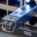
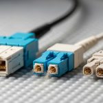
- Inventory and scope: Identify transceivers by part number, vendor, and interface type (10G SFP+, 25G SFP28, 40G QSFP+, 100G QSFP28, OTN/SDH interfaces). Record slot IDs and fiber routes.
- DOM telemetry access: Confirm your platform reads Digital Optical Monitoring (DOM) registers reliably. Examples include Cisco IOS-XE for SFP/SFP+ DOM, Juniper for transceiver diagnostics, or a DCIM/NMS telemetry collector that polls standard DOM fields.
- Standards awareness: DDM behavior is described in IEEE optics monitoring practices and vendor DOM implementations; alarms generally map to received power and bias current thresholds. Use [Source: IEEE 802.3] and vendor datasheets for exact field semantics. anchor-text: IEEE 802.3 optics and monitoring context
- Environmental baselines: Capture ambient temperature and airflow conditions at the rack/ODU. In fronthaul cabinets, a 10 C swing can shift laser bias current and received power.
- Change control: Set a rollback plan. Threshold maintenance should be reversible without opening the cabinet or rebooting the line card.
Expected outcome: You can map each transceiver to its DOM fields, verify telemetry quality, and establish a baseline so your DDM threshold changes are statistically meaningful.
Define what “maintenance” means in DDM thresholds
In predictive maintenance, DDM threshold maintenance is not about making alarms noisier; it is about moving from reactive replacement to early action. Most teams monitor RX optical power (dBm), laser bias current (mA), and module temperature (C). Then they add “soft” actions before the module reaches vendor “hard” alarm limits.
Use actionable alarms, not just absolute limits
Vendor defaults often reflect conservative factory thresholds. A field-maintained approach is to set two layers:
- Warning band: early drift detection (for example, received power trending downward or bias current trending upward).
- Critical band: aligns with or slightly earlier than vendor low/high alarm boundaries so you can intervene before link instability.
Pro Tip: In operational telemetry, the most reliable predictor is often the direction of change (trend slope) rather than a single threshold crossing. A transceiver can stay within nominal ranges for weeks, then fail after a consistent drift pattern in bias current and RX power. Build maintenance rules that trigger on trend + deviation, not only on absolute alarms.
Expected outcome: Your maintenance policy distinguishes warning vs critical events, with trend awareness to reduce false positives.
Build a practical DDM threshold plan using real specs
Thresholds must match the optics type and link budget. A 1310 nm SMF link budget behaves differently from a 850 nm MMF short-reach link, and the same warning thresholds can cause unnecessary maintenance churn. Use wavelength, reach class, connector type, and expected power levels to anchor your thresholds.
Technical specifications comparison (reference optics classes)
The table below is a practical starting point for how teams align thresholds to transceiver class. Always confirm exact values in the transceiver datasheet and your switch platform’s DOM field mapping.
| Transceiver class | Wavelength | Typical reach | Target RX power window | Common alarms | Connector | Operating temp |
|---|---|---|---|---|---|---|
| 10G SR (850 nm) | 850 nm | Up to 300 m OM3/OM4 | -7 to -1 dBm (system-dependent) | Low RX power, high temp | LC | 0 to 70 C (typical) |
| 10G LR (1310 nm) | 1310 nm | Up to 10 km SMF | -15 to -3 dBm (system-dependent) | Low RX power, high bias | LC | -5 to 70 C (typical) |
| 100G QSFP28 FR4 | ~1310/1550 nm mix | Up to 2 km SMF | -10 to -2 dBm (system-dependent) | Per-lane drift, temp | LC | 0 to 70 C (typical) |
To ground this in real deployments, teams often use widely available optics such as Cisco SFP-10G-SR, Finisar FTLX8571D3BCL, or FS.com SFP-10GSR-85 for SR class links, then validate received power and DOM trends after installation. anchor-text: Cisco transceiver documentation hub
How to set warning and critical bands
- Collect baseline for 7 to 14 days: Record RX power, bias current, and temperature at stable traffic hours. Use at least two different ambient conditions if possible (day/night or summer/winter).
- Set warning band at a statistically meaningful deviation: Common practice is to trigger when RX power drops by a configured delta (for example, 1 to 2 dB) from its recent median while temperature remains within normal range. This isolates optical degradation from environmental effects.
- Set critical band near vendor alarm boundaries: Align with your platform’s threshold behavior. If your switch reports “low alarm” at a specific dBm, set critical slightly earlier (for example, 0.5 dB) only if your link budget has enough margin.
- Bias current and temperature correlation: If bias current rises while temperature is stable, suspect aging or contamination at the optical interface. If both rise together, suspect airflow, cabinet heating, or a failing fan.
Expected outcome: Thresholds that reflect your link budget and environment, minimizing false maintenance while catching true degradation early.
Implement monitoring, escalation, and maintenance actions
Threshold maintenance only works if telemetry is reliable and actions are consistent. In the field, the goal is to create a maintenance ticket with enough evidence to avoid guessing: which port, which DOM fields, which trend window, and which physical remediation steps to take.
Operational implementation pattern
- Enable transceiver DOM polling: Ensure the NMS collects RX power, bias current, and temperature at a consistent interval (for example, every 60 seconds). If you poll too slowly, you may miss fast drift events during a hot swap.
- Define escalation rules:
- Warning: Create a “watch” ticket; verify physical cleanliness and check cabinet airflow. No immediate replacement.
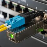
- Critical: Schedule intervention during a maintenance window; verify fiber patching and inspect connectors.
- Hard alarm or link flaps: Treat as “at risk”; plan immediate swap with a known-good spare.
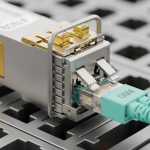
- Track spares by compatibility: Maintain a spare list that matches wavelength, speed, and vendor profile. For example, SR vs LR optics are not interchangeable even when both are “10G SFP+”.
- Document actions: After each maintenance event, record the DOM values before and after swap. This becomes your next baseline.
Expected outcome: A closed-loop process from alarm to physical action, with evidence that improves future threshold accuracy.
Selection criteria and decision checklist for threshold tuning
When you tune DDM threshold maintenance, you are balancing risk, cost, and operational stability. Engineers typically evaluate distance and budget first, then confirm platform compatibility and telemetry features. After that, they consider operating temperature and vendor lock-in risk.
Ordered decision checklist
- Distance and link budget: Match transceiver class to fiber type (SMF vs MMF), connector losses, and expected splice/patch attenuation.
- Data rate and optics format: Ensure the speed class aligns (10G SFP+ vs 25G SFP28 vs 100G QSFP28). Mixed-speed optics can be electrically incompatible.
- Switch and line card compatibility: Some platforms have optics vendor compatibility checks. Confirm with your switch vendor’s supported transceiver list.
- DOM field support and accuracy: Validate that your platform reports RX power and bias current in the expected units and scaling.
- Operating temperature range: In cabinets, the module can run hotter than the room. Choose optics with a temperature rating that matches your worst-case airflow scenario.
- DOM alarm behavior: Check how the platform maps vendor low/high alarms to reported events. Different implementations can shift alarm timing or granularity.
- Vendor lock-in and spare strategy: OEM optics can reduce compatibility risk but increase unit cost. Third-party optics can lower CAPEX but may complicate warranty and DOM interpretation.
Expected outcome: A threshold strategy that survives real operational constraints, not just lab expectations.
Common mistakes and troubleshooting tips for DDM threshold transceiver maintenance
Even well-designed thresholds can fail if the underlying assumptions are wrong. Below are three common field failure modes, with root causes and fixes you can apply quickly.
Failure mode 1: False low RX power alarms after threshold changes
Root cause: Thresholds were set tighter than the natural power variation caused by connector cleaning state, patch cord aging, or day/night temperature shifts.
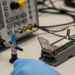
Solution: Re-baseline for 7 to 14 days, then widen the warning band while keeping critical near vendor low alarm. Confirm fiber attenuation with an OTDR or optical power meter and clean connectors before re-tuning thresholds.
Failure mode 2: Bias current alarms without corresponding RX power degradation
Root cause: DOM scaling mismatch or a platform reporting quirk. Some switch platforms interpret bias current fields differently across optic vendors.
Solution: Compare DOM values between a known-good spare and the suspect module. If the bias current interpretation is inconsistent while link performance remains stable, adjust maintenance rules to rely more on RX power trend + lane-level errors (where applicable).
Failure mode 3: Persistent critical alarms due to environmental drift
Root cause: Cabinet airflow failure, clogged filters, or a failing fan tray causing module temperature to rise. RX power may degrade slowly afterward.
Solution: Correlate module temperature with facility telemetry. Fix airflow first (fan replacement, filter cleaning), then perform a post-remediation baseline and re-check thresholds.
Expected outcome: Faster isolation of whether the optics are aging, the telemetry is misinterpreted, or the environment is the true culprit.
Cost and ROI note: what DDM threshold maintenance changes cost-wise
Typical pricing varies widely by speed and vendor. As a realistic range, 10G SR SFP+ optics often land around US$30 to US$120 per unit depending on brand and warranty tier, while 100G QSFP28 optics can range from US$300 to US$1,200+ depending on reach and manufacturer. The ROI comes from reducing unplanned outages and avoiding premature replacements.
In practice, teams reduce truck rolls by scheduling maintenance only when warning trends show consistent degradation. TCO improves when you pair third-party optics with strict compatibility validation and DOM verification, but be honest: OEM optics can lower compatibility risk and speed up RMA processes, which matters in high-availability 5G transport.
Expected outcome: A cost model that accounts for spares, power and labor, and the real probability of optics-related incidents.
FAQ
How often should we check DDM threshold transceiver maintenance alarms?
For most access and enterprise links, polling every 60 seconds is a good balance between responsiveness and load. For high-risk segments like 5G fronthaul aggregation points, consider tighter intervals (for example, 30 seconds) if your telemetry system can handle it. Always test in a pilot window to avoid overwhelming your NMS and switch CPU.
Should we rely on vendor default DDM thresholds?
Vendor defaults are a safe baseline, but they are not always optimal for your specific link budget and environment. In field deployments, teams typically keep critical near vendor boundaries and adjust warning bands based on measured baselines. This reduces false tickets while improving early detection.
Can third-party optics work with our DDM thresholds?
Yes, but you must validate compatibility with your platform’s optics support policy and DOM field behavior. Some switches enforce vendor compatibility lists, and DOM scaling may vary across optics vendors. A controlled test with a known-good spare is the fastest way to confirm that your thresholds behave as expected.
What is the fastest troubleshooting path when a transceiver hits low RX power?
First, clean and reseat connectors if you can do so safely. Next, verify received optical power with a calibrated meter and compare with the link partner expectations. Finally, if the issue follows the transceiver during a swap, replace the module and re-baseline thresholds.
Do temperature alarms always mean the optics are failing?
No. Temperature can rise due to cabinet airflow, blocked vents, or a failing fan tray. Correlate module temperature with facility telemetry and check whether RX power degradation follows temperature rise. Fixing the environment first often prevents repeated optics replacements.
How do we prove threshold changes are effective?
Track the number of warning-to-critical transitions, link error rates, and unplanned downtime before and after changes. A good outcome is fewer critical events and fewer unnecessary maintenance actions. Also review whether any thresholds were adjusted due to false positives, and feed those learnings into your next baseline.
With a disciplined approach to DDM threshold transceiver maintenance—baseline first, tune warning vs critical bands, then automate escalation with evidence—you can move from reactive replacements to predictive optics health. Next, strengthen your overall fiber reliability by reviewing fiber connector cleaning and end-face inspection best practices.
Author bio: I am a telecom engineer who has deployed and maintained 5G transport optics across fronthaul and metro backhaul, including DWDM/OTN and high-density switching with DOM-driven monitoring. I write field-ready procedures that balance uptime, compatibility, and measurable cost impact.